1-104071-1 Tyco Electronics, 1-104071-1 Datasheet - Page 288
1-104071-1
Manufacturer Part Number
1-104071-1
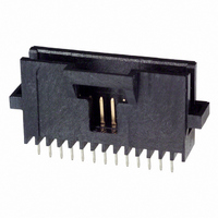
Description
Conn Shrouded Header HDR 12 POS 1.27mm Solder ST Thru-Hole Tube
Manufacturer
Tyco Electronics
Type
Shrouded Headerr
Series
AMPMODU® System 50r
Specifications of 1-104071-1
Pitch
1.27 mm
Number Of Rows
1
Number Of Contacts
12
Gender
HDR
Contact Plating
Gold Over Nickel
Termination Method
Solder
Connector Type
Shrouded
Number Of Positions
12
Number Of Positions Loaded
All
Height Stacking (mating)
0.175", 0.450" (4.45mm, 11.43mm)
Molding Height Above Board
0.390" (9.91mm)
Contact Mating Length
0.125" (3.18mm)
Mounting Type
Through Hole
Termination
Solder
Contact Finish
Gold
Contact Finish Thickness
30µin (0.76µm)
Color
Black
Lead Free Status / RoHS Status
Contains lead / RoHS non-compliant
Features
-
Row Spacing
-
Lead Free Status / RoHS Status
Contains lead / RoHS non-compliant
Other names
1-104071-1
A0102
A0102


7
288
Single Row .156 [3.96]
Centers
Material and Finish
Housing — Black thermoplastic, 94V-0
rated
Contacts — Copper alloy, plated as
follows:
Plating A — Selectively plated
.000030 [0.00076] gold contact area,
with gold flash over .000050 [0.00127]
nickel on entire contact
Plating B — .000079 [0.00201] min.
tin on entire contact
Related Product Data
Mates with —
Machine Applied Posts — page 294
Headers — pages 295-297
Performance Specifications —
page 305
Technical Documents
page 305
Recommended Board
Layouts for Receptacle
Assemblies and Individual
Receptacles (Type C)
Keying Plug
Catalog 1307819
Revised 8-08
www.tycoelectronics.com
(Use in Board Mount
Part No. 86181-2
Receptacles)
Post Entry
Type C
—
are metric equivalents.
Dimensions are in inches and
millimeters unless otherwise
specified. Values in brackets
H
AMPMODU Interconnection System
Mod I Receptacle Assemblies, Horizontal Board Mount,
.031 x .062 [0.79 x 1.57] Centerline
Note: All part numbers are RoHS compliant.
The letter A stamped
on contact indicates
mating end of recep-
tacle.
This configuration recommended
for use with machine applied posts
or headers with a .405 [10.29]
minimum mating end post length.*
The mating post length is depicted by the A dimension on page 294 (machine applied posts) and the C dimension on
pages 295-297 (headers).
H-Receptacle centers may vary depending on requirements. For individual receptacles, minimum nominal centerline
spacing between adjacent receptacles is .125 [3.18] for receptacle assemblies, centerline spacing between adjacent
receptacles is .156 [3.96]. The .003 [0.08] tolerances are not to accumulate over length of board.
[±0.08]
±.003
2H
Dimensions are shown for
reference purposes only.
Specifications subject
to change.
[1.85±0.08]
[±0.08]
±.003
.073±.003
Typ. Dia.
.340
[1.40±0.13]
[8.64+0.13]
.055±.005
[3.96] Typ.
.156
[
+.005
-.000
B ±.015
]
[±0.38]
A
2H
This configuration recommended
for use with machine applied posts
or headers with a .345 [18.76]
minimum mating end post length.*
[±0.08]
±.003
USA: 1-800-522-6752
Canada: 1-905-470-4425
Mexico: 01-800-733-8926
C. America: 52-55-1106-0803
X
H
[±0.08]
±.003
[1.85±0.08]
.073±.003
Typ. Dia.
.340
X
[8.64+0.13]
[
Contact
[1.17]
+.005
-.000
.046
Area
[3.68]
.145
]
[4.62]
2H
.182
This configuration recommended
for use with machine applied posts
or headers with a .500 [12.70]
minimum mating end post length.*
[±0.08]
±.003
South America: 55-11-2103-6000
Hong Kong: 852-2735-1628
Japan: 81-44-844-8013
UK: 44-8706-080-208a
[7.62±0.08]
.300±.003
X-X
H
[±0.08]
±.003
[1.85±0.08]
.073±.003
Typ. Dia.
[0.46]
.018
.340
[4.45±0.18]
[8.46±0.25]
.175±.007
[8.64+0.13]
.333±.010
[2.54]
[
Max.
.100
+.005
-.000
]
Related parts for 1-104071-1
Image
Part Number
Description
Manufacturer
Datasheet
Request
R

Part Number:
Description:
Conn Wire to Board HDR 10 POS 2.54mm Solder ST Thru-Hole
Manufacturer:
TE Connectivity
Datasheet:

Part Number:
Description:
Conn Shrouded Header HDR 10 POS 2mm Solder ST Thru-Hole
Manufacturer:
TE Connectivity
Datasheet:

Part Number:
Description:
Conn Wire to Board HDR 10 POS 2.54mm Solder RA Thru-Hole
Manufacturer:
TE Connectivity
Datasheet:

Part Number:
Description:
Conn IDC Connector PL 10 POS 2.54mm IDT RA Cable Mount Bulk
Manufacturer:
TE Connectivity
Datasheet:

Part Number:
Description:
TIMER, CONNECTOR HOUSING, 10 POS
Manufacturer:
TE Connectivity
Datasheet:

Part Number:
Description:
Switch Tactile OFF (ON) SPST Round Button PC Pins 0.05A 24VDC 1.57N Thru
Manufacturer:
Tyco Electronics
Datasheet:
Part Number:
Description:
Conn Wire to Board RCP 14 POS 2.54mm Solder ST Thru-Hole
Manufacturer:
Tyco Electronics
Datasheet:
Part Number:
Description:
7,5mm MINI HVL CABLE ASSEMBLY length 2000mm White
Manufacturer:
Tyco Electronics
Part Number:
Description:
Tubular 14AWG 18mm 4.7mm Galvanic Tin Bulk
Manufacturer:
Tyco Electronics
Part Number:
Description:
Electromechanical Relay DPDT 15A 48VDC 5.52KOhm Through Hole
Manufacturer:
Tyco Electronics
Datasheet:
Part Number:
Description:
RZ01-1C4-D024
Manufacturer:
Tyco Electronics
Datasheet: