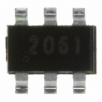
ZXTC2061E6TA Diodes Zetex, ZXTC2061E6TA Datasheet - Page 2

ZXTC2061E6TA
Manufacturer Part Number
ZXTC2061E6TA
Description
TRANSISTOR DUAL 12V 1A SOT23-6
Manufacturer
Diodes Zetex
Datasheet
1.ZXTC2061E6TA.pdf
(8 pages)
Specifications of ZXTC2061E6TA
Transistor Type
NPN, PNP
Current - Collector (ic) (max)
5A, 3.5A
Voltage - Collector Emitter Breakdown (max)
12V
Vce Saturation (max) @ Ib, Ic
180mV @ 100mA, 5A / 200mV @ 350mA, 3.5A
Dc Current Gain (hfe) (min) @ Ic, Vce
480 @ 1A, 2V / 290 @ 1A, 2V
Power - Max
1.1W
Frequency - Transition
260MHz
Mounting Type
Surface Mount
Package / Case
SOT-23-6
Lead Free Status / RoHS Status
Lead free / RoHS Compliant
Current - Collector Cutoff (max)
-
Other names
ZXTC2061E6TR
Absolute maximum and thermal ratings
NOTES:
(a) For a device surface mounted on 15mm x 15mm x 1.6mm FR4 PCB with high coverage of single sided 1oz copper, in
(b) For a device surface mounted on 25mm x 25mm x 1.6mm FR4 PCB with high coverage of single sided 1oz copper, in
(c) For a device surface mounted on 50mm x 50mm x 1.6mm FR4 PCB with high coverage of single sided 2oz copper, in
(d) As above measured at t<5 seconds.
(e) Repetitive rating - pulse width limited by maximum junction temperature. Refer to Transient Thermal Impedance
(f) For device with one active die, both collectors attached to a common sink.
(g) For device with two active dice running at equal power, split sink 50% to each collector.
Issue 1 - November 2007
© Zetex Semiconductors plc 2007
PARAMETER
Collector-base voltage
Collector-emitter voltage
Emitter-base voltage
Continuous collector current
Peak pulse current
Base current
Power dissipation at T
Linear derating factor
Power dissipation at T
Linear derating factor
Power dissipation at T
Linear derating factor
Power dissipation at T
Linear derating factor
Power dissipation at T
Linear derating factor
Operating and storage temperature range
Thermal resistance junction to ambient
Thermal resistance junction to ambient
Thermal resistance junction to ambient
Thermal resistance junction to ambient
Thermal resistance junction to ambient
still air conditions.
still air conditions.
still air conditions.
graph.
A
A
A
A
A
=25°C
=25°C
=25°C
=25°C
=25°C
(c)(f)
(a)(f)
(b)(f)
(b)(g)
(c)(f)
(d)(f)
(a)(f)
(b)(f)
(b)(g)
(c)(f)
(d)(f)
2
Symbol
T
V
V
V
R
R
R
R
R
j
I
, T
P
P
P
P
P
CBO
CEO
EBO
CM
I
I
θJA
θJA
θJA
θJA
θJA
C
B
D
D
D
D
D
stg
-55 to +150
ZXTC2061E6
20(-12)
12(-12)
12(-10)
5(-3.5)
Limit
1(-1)
13.6
179
139
113
113
7(-7)
0.7
5.6
0.9
7.2
1.1
8.8
1.1
8.8
1.7
73
www.zetex.com
mW/°C
mW/°C
mW/°C
mW/°C
mW/°C
°C/W
°C/W
°C/W
°C/W
°C/W
Unit
°C
W
W
W
W
W
A
A
A
V
V
V


