MCR68-002 ON Semiconductor, MCR68-002 Datasheet
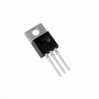
THYRISTOR SCR 12A 50V TO220AB

MCR68-002

Manufacturer Part Number
MCR68-002
Description
THYRISTOR SCR 12A 50V TO220AB
Manufacturer
ON Semiconductor
Datasheet

Specifications of MCR68-002

Scr Type
Standard Recovery
Voltage - Off State
50V
Voltage - Gate Trigger (vgt) (max)
1.5V
Voltage - On State (vtm) (max)
2.2V
Current - On State (it (av)) (max)
8A
Current - On State (it (rms)) (max)
12A
Current - Gate Trigger (igt) (max)
30mA
Current - Hold (ih) (max)
50mA
Current - Off State (max)
10µA
Current - Non Rep. Surge 50, 60hz (itsm)
100A @ 60Hz
Operating Temperature
-40°C ~ 125°C
Mounting Type
Through Hole
Package / Case
TO-220-3 (Straight Leads)
Current - On State (it (rms) (max)
12A
Lead Free Status / RoHS Status
Contains lead / RoHS non-compliant
Other names
MCR68-002OS

Available stocks

Company
Part Number
Manufacturer
Quantity
Price
Part Number:
MCR68-002
Manufacturer:
ON
Quantity:
18 000
MCR68−2
Silicon Controlled Rectifiers
Reverse Blocking Thyristors
Features
Maximum ratings are those values beyond which device damage can occur.
Maximum ratings applied to the device are individual stress limit values (not
normal operating conditions) and are not valid simultaneously. If these limits are
exceeded, device functional operation is not implied, damage may occur and
reliability may be affected.
1. V
2. Ratings apply for t
*For additional information on our Pb−Free strategy and soldering details, please
MAXIMUM RATINGS
© Semiconductor Components Industries, LLC, 2005
December, 2005 − Rev. 2
download the ON Semiconductor Soldering and Mounting Techniques
Reference Manual, SOLDERRM/D.
Peak Repetitive Off−State Voltage (Note 1)
(T
Peak Discharge Current (Note 2)
On-State RMS Current
(180° Conduction Angles; T
Average On-State Current
(180° Conduction Angles; T
Peak Non-Repetitive Surge Current
(1/2 Cycle, Sine Wave, 60 Hz, T
Circuit Fusing Considerations (t = 8.3 ms)
Forward Peak Gate Current
(t ≤ 1.0 ms, T
Forward Peak Gate Power
(t ≤ 1.0 ms, T
Forward Average Gate Power
(t = 8.3 ms, T
Operating Junction Temperature Range
Storage Temperature Range
Mounting Torque
Designed for overvoltage protection in crowbar circuits.
Reliability
High Discharge Current
Resistance and Maximum Power Dissipation and Durability
Glass-Passivated Junctions for Greater Parameter Stability and
Center-Gate Geometry for Uniform Current Spreading Enabling
Small Rugged, Thermowatt Package Constructed for Low Thermal
High Capacitor Discharge Current, 300 Amps
Pb−Free Package is Available*
apply for zero or negative gate voltage; however, positive gate voltage shall
not be applied concurrent with negative potential on the anode. Blocking
voltages shall not be tested with a constant current source such that the
voltage ratings of the devices are exceeded.
duration of an exponentially decaying current waveform, t
5 time constants of an exponentially decaying current pulse.
J
DRM
= *40 to +125°C, Gate Open)
and V
C
C
C
RRM
= 85°C)
= 85°C)
= 85°C)
Rating
for all types can be applied on a continuous basis. Ratings
w
= 1 ms. See Figure 1 for I
(T
J
= 25°C unless otherwise noted)
C
C
= 85°C)
= 85°C)
J
MCR68−2
= 125°C)
Symbol
I
P
V
V
T(RMS)
I
I
P
T(AV)
I
G(AV)
T
DRM,
I
TSM
RRM
I
GM
T
TM
GM
2
stg
J
t
TM
capability for various
−40 to +125
−40 to +150
Value
300
100
8.0
2.0
0.5
8.0
50
12
40
20
w
is defined as
1
in. lb.
Unit
A
°C
°C
W
W
V
A
A
A
A
A
2
s
MCR68−2
MCR68−2G
Preferred devices are recommended choices for future use
and best overall value.
1
2
Device
3
1
2
3
4
ORDERING INFORMATION
12 AMPERES RMS
A
Y
WW
G
AKA = Diode Polarity
A
http://onsemi.com
PIN ASSIGNMENT
CASE 221A−07
50 VOLTS
TO−220AB
= Assembly Location
= Year
= Work Week
= Pb−Free Package
TO−220AB
TO−220AB
STYLE 3
(Pb−Free)
Package
SCRs
Publication Order Number:
Cathode
Anode
Anode
Gate
G
500 Units / Box
500 Units / Box
MARKING
DIAGRAM
MCR68−2G
AY WW
K
Shipping
AKA
MCR68/D

Related parts for MCR68-002

MCR68-002 Summary of contents

Page 1

... MCR68−2G Preferred devices are recommended choices for future use and best overall value. 1 http://onsemi.com SCRs 12 AMPERES RMS 50 VOLTS MARKING DIAGRAM AY WW MCR68−2G AKA TO−220AB CASE 221A− STYLE Assembly Location Y = Year WW = Work Week G = Pb−Free Package AKA = Diode Polarity ...

Page 2

... G 3. Pulse duration p 300 ms, duty cycle p 2%. 4. Ratings apply for ms. See Figure 1 for time constants of an exponentially decaying current pulse. 5. The gate controlled turn-on time in a crowbar circuit will be influenced by the circuit inductance. MCR68− 25°C unless otherwise noted 25° 125° 125° ...

Page 3

... Half Wave 1.0 2.0 5 AVERAGE ON-STATE CURRENT (AMPS) T(AV) Figure 3. Current Derating MCR68−2 on state RRM RRM Reverse Blocking Region (off state) Reverse Avalanche Region Anode − 1.0 0.8 0.6 0.4 0 Figure 2. Peak Capacitor Discharge Current ...

Page 4

... T , JUNCTION TEMPERATURE (°C) J Figure 6. Gate Trigger Current 3.0 2.0 1.0 0.8 0.5 0.3 −60 MCR68− 100 t, TIME (ms) Figure 5. Thermal Response 1 Volts D = 100 1.2 1.0 0.8 0.5 −60 −40 80 100 120 ...

Page 5

... V 0.045 −−− 1.15 −−− Z −−− 0.080 −−− 2.04 STYLE 3: PIN 1. CATHODE 2. ANODE 3. GATE 4. ANODE ON Semiconductor Website: http://onsemi.com Order Literature: http://www.onsemi.com/litorder For additional information, please contact your local Sales Representative. MCR68/D ...

Related keywords