BT151X-500R,127 NXP Semiconductors, BT151X-500R,127 Datasheet - Page 2
BT151X-500R,127
Manufacturer Part Number
BT151X-500R,127
Description
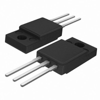
THYRISTOR 500V 12A SOT186A
Manufacturer
NXP Semiconductors
Datasheet
1.BT151X-500R127.pdf
(11 pages)
Specifications of BT151X-500R,127
Package / Case
TO-220-3 Full Pack
Scr Type
Standard Recovery
Voltage - Off State
500V
Voltage - Gate Trigger (vgt) (max)
1.5V
Voltage - On State (vtm) (max)
1.75V
Current - On State (it (av)) (max)
7.5A
Current - On State (it (rms)) (max)
12A
Current - Gate Trigger (igt) (max)
15mA
Current - Hold (ih) (max)
20mA
Current - Off State (max)
500µA
Current - Non Rep. Surge 50, 60hz (itsm)
120A, 132A
Operating Temperature
-40°C ~ 125°C
Mounting Type
Through Hole
Current - On State (it (rms) (max)
12A
Mounting Style
SMD/SMT
Lead Free Status / RoHS Status
Lead free / RoHS Compliant
Other names
934038050127
BT151X-500R
BT151X-500R
BT151X-500R
BT151X-500R


Philips Semiconductors
3. Ordering information
Table 2:
4. Limiting values
Table 3:
In accordance with the Absolute Maximum Rating System (IEC 60134).
[1]
9397 750 13162
Product data sheet
Type number
BT151X-500
BT151X-650
BT151X-800
Symbol
V
I
I
I
I
dI
I
V
P
P
T
T
T(AV)
T(RMS)
TSM
2
GM
stg
j
DRM
t
RGM
GM
G(AV)
T
/dt
Although not recommended, off-state voltages up to 800 V may be applied without damage, but the thyristor may switch to the on-state.
The rate of rise of current should not exceed 15 A/ s.
, V
RRM
Ordering information
Limiting values
Parameter
repetitive peak off-state voltage
average on-state current
RMS on-state current
non-repetitive peak on-state current half sinewave;
I
repetitive rate of rise of on-state
current after triggering
peak gate current
peak reverse gate voltage
peak gate power
average gate power
storage temperature
junction temperature
2
t for fusing
BT151X-500
BT151X-650
BT151X-800
Package
Name
-
Description
plastic single-ended package; isolated heatsink mounted; 1 mounting hole;
3 lead TO-220 ‘full pack’
Rev. 04 — 9 June 2004
Conditions
half sinewave;
T
all conduction angles;
Figure 4
T
surge;
Figure 3
t = 10 ms
I
dI
over any 20 ms period
TM
hs
j
G
= 25 C prior to
t = 10 ms
t = 8.3 ms
/dt 50 mA/ s
= 20 A; I
69 C;
Figure 2
and
G
Figure 1
Figure 5
= 50 mA;
and
[1]
[1]
Min
-
-
-
-
-
-
-
-
-
-
-
-
-
-
40
© Koninklijke Philips Electronics N.V. 2004. All rights reserved.
BT151X series
Max
500
650
800
7.5
12
120
132
72
50
2
5
5
0.5
+150
125
Thyristors
Version
SOT186A
Unit
V
V
V
A
A
A
A
A
A/ s
A
V
W
W
C
C
2
s
2 of 11
Related parts for BT151X-500R,127
Image
Part Number
Description
Manufacturer
Datasheet
Request
R

Part Number:
Description:
SCRs RAIL SCR
Manufacturer:
NXP Semiconductors
Datasheet:
Part Number:
Description:
SCRs RAIL SCR
Manufacturer:
NXP Semiconductors
Datasheet:
Part Number:
Description:
SCRs RAIL SCR
Manufacturer:
NXP Semiconductors
Datasheet:

Part Number:
Description:
THYRISTOR 800V 12A TO-220F
Manufacturer:
NXP Semiconductors
Datasheet:
Part Number:
Description:
THYRISTOR 500V 12A TO-220F
Manufacturer:
NXP Semiconductors
Datasheet:

Part Number:
Description:
SCRs THYRISTOR
Manufacturer:
NXP Semiconductors
Datasheet:
Part Number:
Description:
THYRISTOR 650V 12A TO-220F
Manufacturer:
NXP Semiconductors
Datasheet:

Part Number:
Description:
Passivated thyristors in a full pack, plastic envelope, intended for use in applications requiring high bidirectional blocking voltage capability and high thermal cycling performance
Manufacturer:
NXP Semiconductors
Datasheet:
Part Number:
Description:
Passivated thyristors in a full pack, plastic envelope, intended for use in applications requiring high bidirectional blocking voltage capability and high thermal cycling performance
Manufacturer:
NXP Semiconductors
Datasheet:
Part Number:
Description:
Passivated thyristors in a full pack, plastic envelope, intended for use in applications requiring high bidirectional blocking voltage capability and high thermal cycling performance
Manufacturer:
NXP Semiconductors
Datasheet:
Part Number:
Description:
THYRISTOR 800V 12A SOT186A
Manufacturer:
NXP Semiconductors
Datasheet:
Part Number:
Description:
THYRISTOR 650V 12A SOT186A
Manufacturer:
NXP Semiconductors
Datasheet:
Part Number:
Description:
Thyristors Thyristors
Manufacturer:
NXP Semiconductors
Datasheet:
Part Number:
Description:
NXP Semiconductors designed the LPC2420/2460 microcontroller around a 16-bit/32-bitARM7TDMI-S CPU core with real-time debug interfaces that include both JTAG andembedded trace
Manufacturer:
NXP Semiconductors
Datasheet:

Part Number:
Description:
NXP Semiconductors designed the LPC2458 microcontroller around a 16-bit/32-bitARM7TDMI-S CPU core with real-time debug interfaces that include both JTAG andembedded trace
Manufacturer:
NXP Semiconductors
Datasheet: