10RIA100 Vishay, 10RIA100 Datasheet - Page 2
10RIA100
Manufacturer Part Number
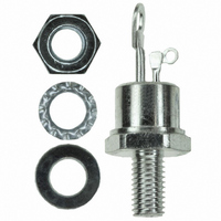
10RIA100
Description
SCR 1000V 10A TO-48
Manufacturer
Vishay
Datasheet
1.VS-10RIA120.pdf
(8 pages)
Specifications of 10RIA100
Scr Type
Standard Recovery
Voltage - Off State
1000V
Voltage - Gate Trigger (vgt) (max)
2V
Voltage - On State (vtm) (max)
1.75V
Current - On State (it (av)) (max)
10A
Current - On State (it (rms)) (max)
25A
Current - Gate Trigger (igt) (max)
60mA
Current - Hold (ih) (max)
130mA
Current - Off State (max)
10mA
Current - Non Rep. Surge 50, 60hz (itsm)
225A, 240A
Operating Temperature
-65°C ~ 125°C
Mounting Type
Chassis, Stud Mount
Package / Case
TO-208AA, TO-48
Current - On State (it (rms) (max)
25A
Breakover Current Ibo Max
240 A
Rated Repetitive Off-state Voltage Vdrm
1000 V
Off-state Leakage Current @ Vdrm Idrm
10 mA
Forward Voltage Drop
1.75 V
Gate Trigger Voltage (vgt)
2 V
Maximum Gate Peak Inverse Voltage
10 V
Gate Trigger Current (igt)
60 mA
Holding Current (ih Max)
130 mA
Mounting Style
Stud
Peak Repetitive Off-state Voltage, Vdrm
1kV
Gate Trigger Current Max, Igt
60mA
Current It Av
25A
On State Rms Current It(rms)
25A
Peak Non Rep Surge Current Itsm 50hz
225A
Lead Free Status / RoHS Status
Lead free / RoHS Compliant
Other names
*10RIA100


10RIA Series
Vishay High Power Products
ELECTRICAL SPECIFICATIONS
Notes
(1)
(2)
www.vishay.com
2
VOLTAGE RATINGS
TYPE
NUMBER
10RIA
ABSOLUTE MAXIMUM RATINGS
PARAMETER
Maximum average on-state current
at case temperature
Maximum RMS on-state current
Maximum peak, one-cycle
non-repetitive surge current
Maximum I
Maximum I
Low level value of threshold voltage
High level value of threshold voltage
Low level value of
on-state slope resistance
High level value of
on-state slope resistance
Maximum on-state voltage
Maximum holding current
Typical latching current
Units may be broken over non-repetitively in the off-state direction without damage, if dI/dt does not exceed 20 A/µs
For voltage pulses with t
2
2
t for fusing
√t for fusing
VOLTAGE
CODE
100
120
10
20
40
60
80
p
≤ 5 ms
V
DRM
/V
AND OFF-STATE VOLTAGE
RRM
SYMBOL
V
For technical questions, contact: ind-modules@vishay.com
V
I
T(RMS)
I
, MAXIMUM REPETITIVE PEAK
I
T(TO)1
T(TO)2
V
T(AV)
I
TSM
I
2
r
r
I
I
2
TM
t1
t2
√t
H
L
t
1000
1200
Medium Power Thyristors
100
200
400
600
800
V
180° conduction, half sine wave
t = 10 ms
t = 8.3 ms
t = 10 ms
t = 8.3 ms
t = 10 ms
t = 8.3 ms
t = 10 ms
t = 8.3 ms
t = 0.1 to 10 ms, no voltage reapplied
(16.7 % x π x I
T
(I > π x I
(16.7 % x π x I
T
(I > π x I
I
T
pk
J
J
J
(Stud Version), 10 A
= T
= T
= 25 °C, anode supply 12 V resistive load
= 32 A, T
J
J
maximum
maximum
T(AV)
T(AV)
J
TEST CONDITIONS
No voltage
reapplied
100 % V
reapplied
No voltage
reapplied
100 % V
reapplied
), T
), T
= 25 °C, t
T(AV)
T(AV)
(1)
J
J
= T
= T
< I < π x I
< I < π x I
J
J
RRM
RRM
maximum
maximum
p
= 10 ms sine pulse
V
RSM
Sinusoidal
half wave,
initial T
T
T(AV)
T(AV)
J
, MAXIMUM NON-REPETITIVE
maximum
),
),
PEAK VOLTAGE
J
=
1100
1300
150
300
500
700
900
V
(2)
VALUES
2550
1.39
16.7
1.75
1.10
24.3
225
240
190
200
255
233
180
165
130
200
10
85
25
Document Number: 93689
AT T
I
DRM
Revision: 06-Jun-08
J
/I
RRM
= T
mA
J
20
10
MAXIMUM
MAXIMUM
UNITS
A
A
mΩ
mA
°C
A
A
A
2
V
V
2
√s
s
Related parts for 10RIA100
Image
Part Number
Description
Manufacturer
Datasheet
Request
R

Part Number:
Description:
357-036-542-201 CARDEDGE 36POS DL .156 BLK LOPRO
Manufacturer:
Vishay
Datasheet:
Part Number:
Description:
357-036-542-201 CARDEDGE 36POS DL .156 BLK LOPRO
Manufacturer:
Vishay
Datasheet:
Part Number:
Description:
357-036-542-201 CARDEDGE 36POS DL .156 BLK LOPRO
Manufacturer:
Vishay
Datasheet:
Part Number:
Description:
357-036-542-201 CARDEDGE 36POS DL .156 BLK LOPRO
Manufacturer:
Vishay
Datasheet:
Part Number:
Description:
357-036-542-201 CARDEDGE 36POS DL .156 BLK LOPRO
Manufacturer:
Vishay
Datasheet:
Part Number:
Description:
357-036-542-201 CARDEDGE 36POS DL .156 BLK LOPRO
Manufacturer:
Vishay
Datasheet:
Part Number:
Description:
357-036-542-201 CARDEDGE 36POS DL .156 BLK LOPRO
Manufacturer:
Vishay
Datasheet:
Part Number:
Description:
357-036-542-201 CARDEDGE 36POS DL .156 BLK LOPRO
Manufacturer:
Vishay
Datasheet:
Part Number:
Description:
357-036-542-201 CARDEDGE 36POS DL .156 BLK LOPRO
Manufacturer:
Vishay
Datasheet:
Part Number:
Description:
357-036-542-201 CARDEDGE 36POS DL .156 BLK LOPRO
Manufacturer:
Vishay
Datasheet:
Part Number:
Description:
357-036-542-201 CARDEDGE 36POS DL .156 BLK LOPRO
Manufacturer:
Vishay
Datasheet:
Part Number:
Description:
357-036-542-201 CARDEDGE 36POS DL .156 BLK LOPRO
Manufacturer:
Vishay
Datasheet:
Part Number:
Description:
357-036-542-201 CARDEDGE 36POS DL .156 BLK LOPRO
Manufacturer:
Vishay
Datasheet:
Part Number:
Description:
357-036-542-201 CARDEDGE 36POS DL .156 BLK LOPRO
Manufacturer:
Vishay
Datasheet:
Part Number:
Description:
357-036-542-201 CARDEDGE 36POS DL .156 BLK LOPRO
Manufacturer:
Vishay
Datasheet: