S8012R Littelfuse / Teccor Brand Thyristors, S8012R Datasheet
S8012R
Specifications of S8012R


Related parts for S8012R


S8012R Summary of contents
Page 1
Sxx12x Series Main Features Symbol Value I 12 T(RMS 400 to 1000 DRM RRM I 20 Absolute Maximum Ratings Symbol Parameter I RMS on-state current T(RMS) I T(AV) I TSM Value for ...
Page 2
Electrical Characteristics (T = 25°C, unless otherwise specified) J Symbol 12V 100°C D DRM 125°C D DRM ...
Page 3
Figure 1: Normalized DC Gate Trigger Current vs. Junction Temperature 2.0 1.5 1.0 0.5 0.0 -40 - Junction Temperature ( (°C) J Figure 3: Normalized DC Holding Current vs. Junction Temperature 2.0 1.5 1.0 0.5 ...
Page 4
Figure 6: Maximum Allowable Case Temperature vs. RMS On-State Current 130 125 120 115 110 105 100 CURRENT WAVEFORM: Sinusoidal LOAD: Resistive or Inductive CONDUCTION ANGLE: 180° RMS On-State Current [I T(RMS) Figure 8: ...
Page 5
Figure 12: Surge Peak On-State Current vs. Number of Cycles 1000 100 Surge Current Duration - Full Cycles Soldering Parameters Reflow Condition - Temperature Min (T ) s(min) Pre Heat - Temperature Max (T ) ...
Page 6
Physical Specifications Terminal Finish Body Material classification 94V-0 Lead Material Design Considerations design practice should limit the maximum continuous semiconductor are proper heat sinking and selection of the main killers of semiconductors. Correct mounting, soldering, and forming of the leads ...
Page 7
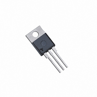
Dimensions — TO-251AA (V/I-Package) — V/I-PAK Through Hole T MEASURING POINT Anode Cathode L F Anode G GATE I Dimensions — TO-252AA (D-Package) — D-PAK Surface Mount ...
Page 8
Product Selector Voltage Part Number 400V 600V Sxx12R X X Sxx12V X X Sxx12D X X Packing Options Part Number Marking Sxx12R Sxx12R Sxx12RTP Sxx12R Sxx12DTP Sxx12D Sxx12DRP Sxx12D Sxx12VTP Sxx12V Note Voltage TO-252 Embossed Carrier Reel Pack ...