S4004VS2TP Littelfuse / Teccor Brand Thyristors, S4004VS2TP Datasheet
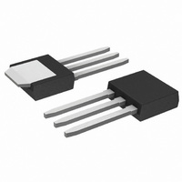
SCR SENS 400V 4A TO-251

S4004VS2TP

Manufacturer Part Number
S4004VS2TP
Description
SCR SENS 400V 4A TO-251
Manufacturer
Littelfuse / Teccor Brand Thyristors
Datasheet

Specifications of S4004VS2TP

Scr Type
Sensitive Gate
Voltage - Off State
400V
Voltage - Gate Trigger (vgt) (max)
800mV
Voltage - On State (vtm) (max)
1.6V
Current - On State (it (av)) (max)
2.5A
Current - On State (it (rms)) (max)
4A
Current - Gate Trigger (igt) (max)
200µA
Current - Hold (ih) (max)
6mA
Current - Off State (max)
2µA
Current - Non Rep. Surge 50, 60hz (itsm)
25A, 30A
Operating Temperature
-40°C ~ 110°C
Mounting Type
Through Hole
Package / Case
IPak, TO-251, DPak, VPak (3 straight leads + tab)
Current - On State (it (rms) (max)
4A
Lead Free Status / RoHS Status
Lead free / RoHS Compliant
Specifications are subject to change without notice.
Please refer to http://www.littelfuse.com for current information.
©2010 Littelfuse, Inc
Symbol
Main Features
Absolute Maximum Ratings
I
I
I
I
I
I
di/dt
I
P
T
T
T(RMS)
T(RMS)
TSM
2
J
DRM
t
stg
Symbol
RRM
Sxx04xSx Series
Operating junction temperature range
Critical rate of rise of on-state current
Peak non-repetitive surge current
Average gate power dissipation
Storage temperature range
Average on-state current
400 to 600
50 to 500
RMS on-state current
Value
I
Peak gate current
2
4
Parameter
Teccor
4 Amp Sensitive SCRs
Unit
μA
A
®
Revised: July 29, 2010 09:54 AM
brand Thyristors
209
Description
Excellent unidirectional switches for phase control
applications such as heating and motor speed controls.
Sensitive gate SCRs are easily triggered with microAmps
of current as furnished by sense coils, proximity switches,
and microprocessors.
Features & Benefits
Applications
Typical applications are capacitive discharge systems for
strobe lights, nailers, staplers and gas engine ignition. Also
controls for power tools, home/brown goods and white
goods appliances.
Schematic Symbol
junctions
Test Conditions
T
T
J
J
A
(initial) = 25°C
(initial) = 25°C
t
T
T
T
T
p
J
J
C
C
= 8.3 ms
= 110°C
= 110°C
= 95°C
= 75°C
J
= 110°C
-40 to 150
-40 to 110
30 A
Value
2.5
3.7
0.1
25
30
50
4
1
G
Sxx04xSx Series
Unit
A/μs
A
W
°C
°C
A
A
A
A
K
2
s

Related parts for S4004VS2TP

S4004VS2TP Summary of contents

Page 1

Sxx04xSx Series Main Features Symbol Value I 4 T(RMS) 400 to 600 DRM RRM 500 Absolute Maximum Ratings Symbol Parameter I RMS on-state current T(RMS) I Average on-state current I Peak non-repetitive surge current TSM I 2 ...

Page 2

Electrical Characteristics — 25°C, unless otherwise specified) J Symbol Test Conditions I D dv/ 1kΩ D DRM ; DRM 10μ 20mA (initial); ...

Page 3

Figure 1: Normalized DC Gate Trigger Current vs. Junction Temperature 4.0 3.0 2.0 1.0 0.0 -40 - Junction Temperature ( (°C) J Figure 3: Normalized DC Holding Current vs. Junction Temperature 3.0 2.5 2.0 1.5 ...

Page 4

Figure 7: Maximum Allowable Case Temperature vs. RMS On-State Current 115 110 Sxx04VSy 105 Sxx04DSy 100 CURRENT WAVEFORM: Sinusoidal LOAD: Resistive or Inductive 75 CONDUCTION ANGLE: 180° 70 0.0 0.5 1.0 1.5 2.0 2.5 RMS On-State ...

Page 5

Figure 13: Surge Peak On-State Current vs. Number of Cycles 100.0 Sxx04VSy Sxx04DSy 10.0 1.0 0 Surge Current Duration -- Full Cycles Figure 14: Simple Test Circuit for Gate Trigger Voltage and Current Reset Normally-closed Pushbutton 100 + ...

Page 6

Soldering Parameters Reflow Condition - Temperature Min (T ) s(min) Pre Heat - Temperature Max (T ) s(max) - Time (min to max Average ramp up rate (Liquidus Temp peak ...

Page 7

Dimensions — TO-251AA (V/I-Package) — V/I-PAK Through Hole T MEASURING POINT Anode Cathode F Anode G GATE I Dimensions — TO-252AA (D-Package) — D-PAK Surface Mount ...

Page 8

Product Selector Voltage Part Number 400V 600V Sxx04DS1 X X Sxx04DS2 Packing Options Part Number Marking Sxx04DSyTP Sxx04DSy Sxx04DSyRP Sxx04DSy Note voltage sensitivity TO-252 Embossed Carrier Reel Pack (RP) Specs ...

Related keywords