CS8-08IO2 IXYS, CS8-08IO2 Datasheet
Manufacturer Part Number
CS8-08IO2
Description
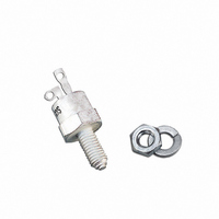
SCR PHASE CONTROL 800V 16A TO-64
Specifications of CS8-08IO2
Scr Type
Standard Recovery
Voltage - Off State
800V
Voltage - Gate Trigger (vgt) (max)
2.5V
Voltage - On State (vtm) (max)
1.6V
Current - On State (it (av)) (max)
16A
Current - On State (it (rms)) (max)
25A
Current - Gate Trigger (igt) (max)
30mA
Current - Hold (ih) (max)
80mA
Current - Off State (max)
3mA
Current - Non Rep. Surge 50, 60hz (itsm)
250A, 270A
Operating Temperature
-40°C ~ 125°C
Mounting Type
Chassis, Stud Mount
Package / Case
TO-64
Current - On State (it (rms) (max)
25A
Vrrm, Vdrm, (v)
800
Itavm, (a)
16
@ Tc, (°c)
85
Itrms, (a)
25
Itsm, 10ms, Tvj = 45°c, (a)
250
Itsm, 8.33ms, Tvj = 45°c, (a)
270
[dv/dt] C, (v/µs)
1000
Vt0, (v)
1.00
Rt, (mohm)
18
Tvjm, (°c)
125
Rthjc, Max, (k/w)
1.50
Rthch, (k/w)
1.00
Package Style
TO-64
Lead Free Status / RoHS Status
Lead free / RoHS Compliant
Data according to IEC 60747
IXYS reserves the right to change limits, test conditions and dimensions
Phase Control Thyristors
Symbol
I
I
I
I
(di/dt)
(dv/dt)
P
P
V
T
T
T
M
Weight
© 2000 IXYS All rights reserved
1300
V
V
T(RMS)
T(AV)M
TSM
2
900
t
VJ
VJM
stg
GM
G(AV)
RGM
d
V
RSM
DSM
cr
cr
1200
V
V
Test Conditions
T
T
T
V
T
V
T
V
T
V
T
f = 50 Hz, t
V
I
di
T
R
T
I
Mounting torque
800
G
T
RRM
DRM
V
VJ
case
VJ
VJ
VJ
VJ
VJ
VJ
VJ
R
R
R
R
D
G
GK
= I
= 0.2 A
/dt = 0.2 A/ms
= 0
= 0
= 0
= 0
= 2/3 V
= 45°C;
= T
= 45°C
= T
= T
= T
= T
= ¥; method 1 (linear voltage rise)
T(AV)M
= T
= 85°C; 180° sine
VJM
VJM
VJM
VJM
VJM
VJM
;
DRM
P
=200 ms
Type
CS 8-08io2
CS 8-12io2
t = 10 ms (50 Hz), sine
t = 8.3 ms (60 Hz), sine
t = 10 ms (50 Hz), sine
t = 8.3 ms (60 Hz), sine
t = 10 ms (50 Hz), sine
t = 8.3 ms (60 Hz), sine
t = 10 ms (50 Hz), sine
t = 8.3 ms (60 Hz), sine
repetitive, I
non repetitive, I
V
t
t
P
P
DR
=
= 300 ms
= 2/3 V
30 ms
T
DRM
= 48 A
T
= I
T(AV)M
-40...+125
-40...+125
Maximum Ratings
1
1000
250
270
200
220
310
306
200
200
150
500
125
0.5
2.5
25
16
10
10
22
5
6
3
A/ms
A/ms
V/ms
lb.in.
Nm
A
A
A
A
°C
°C
°C
W
W
W
A
A
A
A
A
A
V
g
2
2
2
2
s
s
s
s
2
V
I
I
TO-64
1 = Anode, 2 = Cathode, 3 = Gate
Features
Applications
Advantages
Dimensions in mm (1 mm = 0.0394")
T(RMS)
T(AV)M
Thyristor for line frequencies
International standard package
JEDEC TO-64
Planar glassivated chip
Long-term stability of blocking
currents and voltages
Motor control
Power converter
AC power controller
Space and weight savings
Simple mounting
Improved temperature and power
cycling
RRM
= 800-1200 V
= 25 A
= 16 A
3
1
2
M5
CS 8
1 - 3
Related parts for CS8-08IO2
CS8-08IO2 Summary of contents
... T(AV)M P G(AV) V RGM VJM T stg M Mounting torque d Weight Data according to IEC 60747 IXYS reserves the right to change limits, test conditions and dimensions © 2000 IXYS All rights reserved 1 Maximum Ratings 25 16 250 270 200 220 310 306 200 200 = 48 A 150 ...
... 25° =125° Fig. 1 Gate voltage and gate current Triggering no possible safe © 2000 IXYS All rights reserved Characteristic Values £ DRM £ = 125°C) VJ £ £ £ £ £ DRM £ £ 100 = ¥ £ GK £ DRM = 300 ms; di/dt = -20 A/ms typ ...
... T(AV)M Fig. 7 Power dissipation versus on-state current and ambient temperature 3.5 K/W 3.0 2.5 Z thJH 2.0 1.5 1.0 0.5 0 Fig. 8 Transient thermal impedance junction to heatsink © 2000 IXYS All rights reserved 1000 800 A s 600 400 T = 45°C VJ 200 T = 125°C ...
Related keywords
- CS8-08IO2 datasheet
- CS8-08IO2 data sheet
- CS8-08IO2 pdf datasheet
- CS8-08IO2 component
- CS8-08IO2 part
- CS8-08IO2 distributor
- CS8-08IO2 RoHS
- CS8-08IO2 datasheet download