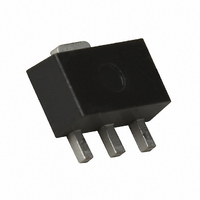
NESG250134-T1-AZ CEL, NESG250134-T1-AZ Datasheet

NESG250134-T1-AZ
Specifications of NESG250134-T1-AZ
Available stocks
Related parts for NESG250134-T1-AZ
NESG250134-T1-AZ Summary of contents
Page 1
... POWER MINIMOLD (34 PACKAGE) ORDERING INFORMATION PART NUMBER ORDER NUMBER NESG250134-AZ NESG250134-AZ NESG250134-T1-AZ NESG250134-T1-AZ Note 1. Contains lead in the part except the electrode terminals. Remark To order evaluation samples, contact your nearby sales office. Unit sample quantity is 25 pcs. ABSOLUTE MAXIMUM RATINGS PARAMETER Collector to Base Voltage ...
Page 2
THERMAL RESISTANCE (T PARAMETER Thermal Resistance from Junction to Ambient Note Mounted on 34 × 0.8 mm (t) glass epoxy PWB RECOMMENDED OPERATING RANGE PARAMETER Collector to Emitter Voltage Collector Current Input Power Note Note Input power under ...
Page 3
ELECTRICAL CHARACHTERISTICS PARAMETER SYMBOL DC Characteristics Collector Cut-off Current Emitter Cut-off Current DC Current Gain RF Characteristics Gain Bandwidth Product Insertion Power Gain Maximum Stable Gain Linear gain (1) Linear gain (2) Output Power (1) Output Power (2) Collector Efficiency ...
Page 4
TYPICAL CHARACHTERISTICS TOTAL POWER DISSIPATION vs. AMBIENT TEMPERATURE 2.0 Mounted on Glass epoxy PWB 2 (34.2 cm × 0.8 mm (t) ) 1.6 1.5 1.2 0.8 Nature Neglect 0 Ambient Temperature T COLLECTOR CURRENT vs. BASE ...
Page 5
DC CURRENT GAIN vs. COLLECTOR CURRENT 1,000 100 10 10 100 Collector Current I GAIN BANDWIDTH PRODUCT vs. COLLECTOR CURRENT 460 MHz 100 Collector Current I ...
Page 6
INSERTION POWER GAIN, MAG, MSG vs. FREQUENCY 40 35 MSG 30 MAG 21e 0 0.1 1 Frequency f (GHz) INSERTION POWER GAIN, MAG, MSG vs. COLLECTOR CURRENT 30 25 MSG 21e ...
Page 7
INSERTION POWER GAIN, MAG, MSG vs. COLLECTOR CURRENT 30 25 MSG 21e 100 Collector Current I OUTPUT POWER, POWER GAIN, COLLECTOR CURRENT, COLLECTOR EFFICIENCY vs. INPUT POWER 3.6 ...
Page 8
PA EVALUATION BOARD (f = 460 MHz Notes 1. 38 × 0.8 mm double sided copper clad glass epoxy PWB. 2. Back side: GND pattern 3. Solder gold plated on pattern 4. ...
Page 9
COMPONENT LIST VALUE C3 0 C9, C10 100 nF L1 100 Ω PA EVALUATION ...
Page 10
DISTORTION EVALUATION BOARD Notes 1. 38 × 0.8 mm, double sided copper clad glass epoxy PWB. 2. Back side: GND pattern 3. Solder gold plated on pattern 4. : Through holes DISTORTION ...
Page 11
COMPONENT LIST VALUE C3 0 C10, C12 100 nF C11 1 μF L1 100 ...
Page 12
... These NEC products are not intended for use in life support devices, appliances, or systems where the malfunction of these products can reasonably be expected to result in personal injury. The customers of CEL using or selling these products for use in such applications their own risk and agree to fully indemnify CEL for all damages resulting from such improper use or sale. ...
Page 13
... CAS numbers and other limited information may not be available for release event shall CEL’s liability arising out of such information exceed the total purchase price of the CEL part(s) at issue sold by CEL to customer on an annual basis. ...


