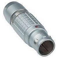
FGG.0B.302.CLAD31 LEMO, FGG.0B.302.CLAD31 Datasheet - Page 9

FGG.0B.302.CLAD31
Manufacturer Part Number
FGG.0B.302.CLAD31
Description
Conn Circular M 2 POS Solder ST Cable Mount 2 Terminal 1 Port
Manufacturer
LEMO
Type
Circularr
Series
Br
Datasheet
1.GMA.0B.030.DR.pdf
(186 pages)
Specifications of FGG.0B.302.CLAD31
Gender
PL
Termination Method
Solder
Mounting
Cable Mount
Body Orientation
Straight
Connector Body Material
Brass
Contact Gender
Pin
Connector Mounting
Cable
Insert Arrangement
302
Connector Type
Circular Industrial
Lead Free Status / RoHS Status
- Current page: 9 of 186
- Download datasheet (12Mb)
Verify the fitting to your wire
Verify if the selected contact diameter (ø A) of the LEMO connector fits to your cable wire diameter (AWG number or
max. available section).
Note:
1)
2)
3)
4)
5)
www.lemo.com
fig. 1
fig. 2
contact retention force in the insulator (according to IEC 60512-8 test 15 a).
for 00 multipole series.
for S, E, 2C, 2G and 1D series.
for a given AWG, the diameter of some stranded conductor designs is larger than the solder cup diameter. Make sure that the maximum conductor
diameter is smaller than ø C.
for 00 multipole series or for 0B and 1B series with male contacts.
ø A
ø A
ø A
ø A
ø A
ø A
ø A
ø A
ø A
Contact type
Print (elbow)
Solder
Crimp
Print
L
L
L
ø C
ø C
ø C
ø C
ø C
ø C
ø C
ø C
ø C
(mm)
12.0
ø A
0.5
0.5
0.7
0.7
0.9
1.3
1.6
2.0
3.0
4.0
5.0
6.0
8.0
0.5
0.7
0.9
1.3
1.6
2.0
3.0
4.0
2)
3)
5)
Contact
L dimensions and C are detailed in the section on PCB drilling pattern.
L dimensions and C are detailed in the section on PCB drilling pattern.
11.50
(mm) per fig.
0.45
0.80
0.80
1.00
1.40
1.80
2.70
3.70
5.20
5.20
7.00
0.45
0.80
0.45
1.10
0.80
0.45
1.40
1.10
0.80
1.90
1.40
2.40
1.90
2.90
4.00
0.40
0.60
ø C
2)
3)
Form
–
–
–
–
–
–
–
–
–
–
–
–
–
–
1
1
2
1
2
2
1
2
2
1
2
1
2
1
1
AWG
max.
28
28
24
22
22
20
16
14
10
10
–
–
–
–
–
–
–
–
–
–
–
–
–
–
–
–
–
–
–
See page 156 and 159.
See page 157 and 160.
Solid
Section
(mm
max.
0.09
0.09
0.25
0.34
0.34
0.50
1.00
1.50
4.00
6.00
–
–
–
–
–
–
–
–
–
–
–
–
–
–
–
–
–
–
–
2
)
min.
32
26
32
24
26
32
20
24
26
18
22
16
18
14
12
Conductor
–
–
–
–
–
–
–
–
–
–
–
–
–
–
AWG
max.
30
28
26
22
22
20
18
16
12
10
28
22
28
20
22
28
18
20
22
14
18
12
14
10
10
8
8
4
0
Stranded
4)
4)
4)
4)
4)
4)
4)
4)
4)
Section (mm
0.035
0.140
0.035
0.250
0.140
0.035
0.500
0.250
0.140
1.000
0.340
1.500
1.000
2.500
4.000
min.
–
–
–
–
–
–
–
–
–
–
–
–
–
–
10.00
10.00
21.00
50.00
max.
0.05
0.09
0.14
0.34
0.34
0.50
1.00
1.50
4.00
6.00
0.09
0.34
0.09
0.50
0.34
0.09
1.00
0.50
0.34
1.50
1.00
2.50
1.50
4.00
6.00
2
)
®
F
(N)
12
22
30
40
50
65
75
90
r
–
–
–
–
–
–
–
–
–
–
–
–
–
–
1)
Note
●
●
●
●
●
●
●
●
●
●
●
●
●
●
●
●
●
●
7
®
Related parts for FGG.0B.302.CLAD31
Image
Part Number
Description
Manufacturer
Datasheet
Request
R

Part Number:
Description:
RF Connectors ADAPTOR SOCKET TO BNC PLUG
Manufacturer:
LEMO
Datasheet:

Part Number:
Description:
RF Connectors ADAPT-BNC(UG88U)COAX
Manufacturer:
LEMO
Datasheet:

Part Number:
Description:
RF Connectors BNC ADAPTER 50 OHM
Manufacturer:
LEMO
Datasheet:

Part Number:
Description:
LEMO, SPRING LOADED DUSTCAP
Manufacturer:
LEMO
Datasheet:

Part Number:
Description:
Circular Push Pull Connectors CONNECTOR WRENCH FOR LEMO
Manufacturer:
LEMO

Part Number:
Description:
Specifications: Connector Type: Plug, Male Pins ; Shell Size - Insert: 114 ; Mounting Type: Free Hanging (In-Line) ; Fastening Type: Threaded ; Features: Shielded ; Packaging: Bulk ; Number of Positions: 114 ; Termination: Crimp ; Shell Material, Fin
Manufacturer:
LEMO

Part Number:
Description:
Specifications: Connector Style: - ; Connector Type: Plug ; Simplex/Duplex: Duplex ; Mode: Singlemode ; Fiber Diameter: 125
Manufacturer:
LEMO


