MRF6VP2600HR6 Freescale Semiconductor, MRF6VP2600HR6 Datasheet
MRF6VP2600HR6
Specifications of MRF6VP2600HR6
Available stocks


Related parts for MRF6VP2600HR6

MRF6VP2600HR6 Summary of contents
Page 1
... PART IS PUSH- -PULL inA GSA outA inB GSB outB (Top View) Figure 1. Pin Connections Symbol Value Unit V --0.5, +110 Vdc DSS V --6.0, +10 Vdc +150 °C stg T 150 ° 225 °C J (2,3) Symbol Value Unit R °C/W θJC 0.20 0.14 0.16 MRF6VP2600HR6 /V DSA /V DSB 1 ...
Page 2
... Input Return Loss Typical Performance — 88- -108 MHz (In Freescale 88--108 MHz Test Fixture, 50 ohm system Power Gain Drain Efficiency Input Return Loss 1. Each side of device measured separately. 2. Measurement made with device in push--pull configuration. MRF6VP2600HR6 2 = 25°C unless otherwise noted) A Symbol I GSS V ...
Page 3
... Microstrip Z9, Z10 0.200″ x 0.518″ Microstrip Z11, Z12 0.375″ x 0.214″ Microstrip Figure 2. MRF6VP2600HR6 Test Circuit Schematic Table 5. MRF6VP2600HR6 Test Circuit Component Designations and Values Part B1 95 Ω, 100 MHz Long Ferrite Bead Chip Capacitor ...
Page 4
... B1 C13 C16 C12 + C11 C15 L3 C14 C10 wrapped around R1. Figure 3. MRF6VP2600HR6 Test Circuit Component Layout MRF6VP2600HR6 4 L4, R1 (on side) -- C23 C22 C21 C20 C25 C24 -- -- C18 C19 C17 MRF6VP2600H 225 MHz Rev Device Data Freescale Semiconductor ...
Page 5
... P3dB = 59.7 dBm (938 W) P2dB = 59.1 dBm (827 Vdc 2600 mA 225 MHz DD DQ Pulse Width = 12 μsec, Duty Cycle = INPUT POWER (dBm) in Input Power 2600 mA DQ η D 100 P , OUTPUT POWER (WATTS) PULSED out versus Output Power MRF6VP2600HR6 T = 175_C J 100 Ideal Actual 1000 5 ...
Page 6
... Vdc 222 MHz 228 MHz DD 1300 mA Two--Tone Measurements, 6 MHz Tone Spacing 23.5 20 100 P , OUTPUT POWER (WATTS) PEP out Figure 12. Two- -Tone Power Gain versus Output Power MRF6VP2600HR6 6 -- Vdc 500 W (PEP out Two--Tone Measurements --20 --30 3rd Order --40 5th Order --50 ...
Page 7
... ACPR Measured at 4 MHz Offset from Center Frequency 8K Mode DVB--T OFDM 64 QAM Data Carrier Modulation, 5 Symbols --4 --3 --2 -- FREQUENCY (MHz Vdc 225 MHz = 1300 mA 1800 mA 2600 mA 100 P , OUTPUT POWER (WATTS) AVG. out versus Output Power --56 --30_C --58 --60 η D -- 2600 MHz DQ --66 --68 400 MRF6VP2600HR6 4 5 200 7 ...
Page 8
... Figure 19. MTTF versus Junction Temperature - - CW MRF6VP2600HR6 8 TYPICAL CHARACTERISTICS 110 130 150 170 190 210 T , JUNCTION TEMPERATURE (°C) J This above graph displays calculated MTTF in hours when the device is operated Vdc 125 W Avg., and η DD out MTTF calculator available at http://www.freescale.com/rf. Select Software & Tools/Development Tools/Calculators to access MTTF calculators by product ...
Page 9
... DD DQ out source load MHz Ω Ω 225 1.42 + j8.09 4.45 + j1. Test circuit impedance as measured from source gate to gate, balanced configuration Test circuit impedance as measured from load drain to drain, balanced configuration. Device + Under -- Test -- + Z Z source load Output Matching Network MRF6VP2600HR6 9 ...
Page 10
... MRF6VP2600KH Rev. 2 Figure 21. MRF6VP2600HR6 Test Circuit Component Layout — 88- -108 MHz Table 6. MRF6VP2600HR6 Test Circuit Component Designations and Values — 88- -108 MHz Part B1 95 Ω, 100 MHz Long Ferrite Bead C1 6.8 μ Chip Capacitor Chip Capacitor C3, C13, C14 1000 pF Chip Capacitors C4, C5 μ ...
Page 11
... MHz Vdc 150 108 MHz MHz 88 MHz η D 200 300 400 500 600 700 P , OUTPUT POWER (WATTS) out Vdc 150 600 W, CW out G ps η 102 f, FREQUENCY (MHz) versus Frequency — 88- -108 MHz MHz 70 88 MHz 800 106 110 MRF6VP2600HR6 11 ...
Page 12
... Ω o Input Matching Network Figure 24. Series Equivalent Source and Load Impedance — 88- -108 MHz MRF6VP2600HR6 MHz f = 108 MHz Z source Z load f = 108 MHz MHz Vdc 150 mA 600 W Avg out source load MHz Ω Ω 88 3.20 + j14.50 10.35 + j2.80 98 4.20 + j15.00 9.50 + j3.00 108 4 ...
Page 13
... L2 C6 C10 B2 C8 C12 *Mounted on side Figure 25. MRF6VP2600HR6 Test Circuit Component Layout — 352.2 MHz Table 7. MRF6VP2600HR6 Test Circuit Component Designations and Values — 352.2 MHz Part B1 Ω, 100 MHz Short Ferrite Beads C1, C2 100 pF Chip Capacitors C3*, C24 Chip Capacitors C4* ...
Page 14
... TYPICAL CHARACTERISTICS — 352.2 MHz Figure 26. CW Power Gain and Drain Efficiency MRF6VP2600HR6 Vdc 150 352.2 MHz η D 100 P , OUTPUT POWER (WATTS) CW out versus Output Power 1000 RF Device Data Freescale Semiconductor ...
Page 15
... Z Z source MHz Ω 352.2 1.10 + j3.80 2.26 + j3. Test circuit impedance as measured from source gate to gate, balanced configuration Test circuit impedance as measured from load drain to drain, balanced configuration. Device + Under -- Test -- + Z Z source load Ω o load Ω Output Matching Network MRF6VP2600HR6 15 ...
Page 16
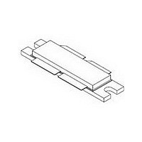
... MRF6VP2600HR6 16 PACKAGE DIMENSIONS RF Device Data Freescale Semiconductor ...
Page 17
... RF Device Data Freescale Semiconductor MRF6VP2600HR6 17 ...
Page 18
... The 88--108 MHz application circuit is also now a more compact size., p. 10--12 5.1 July 2010 • Fig. 24, Series Impedance for 88--108 MHz, table and plot updated to reflect correct location load MRF6VP2600HR6 18 REVISION HISTORY Description and Z values from 1.58 + j6.47 to 1.42 + j8.09 and 4.60 + j1.85 to 4.45 + j1.16 and re- load copy to read ” ...
Page 19
... Freescale Semiconductor was negligent regarding the design or manufacture of the part. Freescalet and the Freescale logo are trademarks of Freescale Semiconductor, Inc. All other product or service names are the property of their respective owners. © Freescale Semiconductor, Inc. 2008--2010. All rights reserved. MRF6VP2600HR6 19 ...