MRF9030LR1 Freescale Semiconductor, MRF9030LR1 Datasheet - Page 5
MRF9030LR1
Manufacturer Part Number
MRF9030LR1
Description
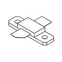
IC MOSFET RF N-CHAN NI-360
Manufacturer
Freescale Semiconductor
Specifications of MRF9030LR1
Transistor Type
N-Channel
Frequency
945MHz
Gain
19dB
Voltage - Rated
68V
Current Rating
10µA
Current - Test
250mA
Voltage - Test
26V
Power - Output
30W
Package / Case
NI-360
Channel Type
N
Channel Mode
Enhancement
Drain Source Voltage (max)
68V
Power Gain (typ)@vds
19dB
Frequency (max)
1GHz
Package Type
NI-360
Pin Count
3
Forward Transconductance (typ)
3S
Input Capacitance (typ)@vds
49.5@26VpF
Output Capacitance (typ)@vds
26.5@26VpF
Reverse Capacitance (typ)
1@26VpF
Operating Temp Range
-65C to 200C
Drain Efficiency (typ)
60%
Mounting
Screw
Mode Of Operation
2-Tone
Number Of Elements
1
Power Dissipation (max)
92000mW
Vswr (max)
10
Screening Level
Military
Lead Free Status / RoHS Status
Lead free / RoHS Compliant
Noise Figure
-
Lead Free Status / Rohs Status
Compliant
Available stocks
Company
Part Number
Manufacturer
Quantity
Price
Company:

Part Number:
MRF9030LR1
Manufacturer:
FREESCALE
Quantity:
1 400
Part Number:
MRF9030LR1
Manufacturer:
FREESCALE
Quantity:
20 000


MOTOROLA RF DEVICE DATA
−70
19.5
18.5
17.5
−10
−20
−30
−40
−50
−60
20
19
18
17
0
Figure 6. Intermodulation Distortion Products
V
I
f1 = 945 MHz, f2 = 945.1 MHz
DQ
Figure 4. Power Gain versus Output Power
I
300 mA
250 mA
200 mA
DD
DQ
= 250 mA
= 26 Vdc
= 375 mA
1
1
P
P
out
out
, OUTPUT POWER (WATTS) PEP
versus Output Power
, OUTPUT POWER (WATTS) PEP
3rd Order
5th Order
7th Order
20
19
18
17
16
15
14
13
12
10
Figure 3. Class AB Broadband Circuit Performance
10
Freescale Semiconductor, Inc.
930
V
f1 = 945 MHz, f2 = 945.1 MHz
For More Information On This Product,
DD
G
η
IMD
IRL
ps
= 26 Vdc
935
TYPICAL CHARACTERISTICS
Go to: www.freescale.com
100
V
P
I
Two −Tone, 100 kHz Tone Spac−
ing
DQ
100
DD
out
f, FREQUENCY (MHz)
940
= 250 mA
= 26 Vdc
= 30 W (PEP)
945
22
20
18
16
14
12
10
−60
−20
−30
−40
−50
0.1
950
Figure 7. Power Gain and Efficiency versus
V
I
f = 945 MHz
DQ
DD
Figure 5. Intermodulation Distortion versus
V
f1 = 945 MHz, f2 = 945.1 MHz
DD
= 250 mA
= 26 Vdc
= 26 Vdc
955
1
P
out
P
, OUTPUT POWER (WATTS) AVG.
out
I
DQ
, OUTPUT POWER (WATTS) PEP
960
1
Output Power
= 200 mA
50
45
40
35
−30
−32
−34
−36
−38
Output Power
300 mA
375 mA
G
η
MRF9030LR1 MRF9030LSR1
ps
10
−10
−12
−14
−16
−18
10
250 mA
100
100
60
50
40
30
20
10
0
5
Related parts for MRF9030LR1
Image
Part Number
Description
Manufacturer
Datasheet
Request
R

Part Number:
Description:
N - Channel Enhancement - Mode Lateral Mosfet
Manufacturer:
Freescale Semiconductor, Inc
Datasheet:
Part Number:
Description:
Manufacturer:
Freescale Semiconductor, Inc
Datasheet:
Part Number:
Description:
Manufacturer:
Freescale Semiconductor, Inc
Datasheet:
Part Number:
Description:
Manufacturer:
Freescale Semiconductor, Inc
Datasheet:
Part Number:
Description:
Manufacturer:
Freescale Semiconductor, Inc
Datasheet:
Part Number:
Description:
Manufacturer:
Freescale Semiconductor, Inc
Datasheet:
Part Number:
Description:
Manufacturer:
Freescale Semiconductor, Inc
Datasheet:
Part Number:
Description:
Manufacturer:
Freescale Semiconductor, Inc
Datasheet:
Part Number:
Description:
Manufacturer:
Freescale Semiconductor, Inc
Datasheet:
Part Number:
Description:
Manufacturer:
Freescale Semiconductor, Inc
Datasheet:
Part Number:
Description:
Manufacturer:
Freescale Semiconductor, Inc
Datasheet:
Part Number:
Description:
Manufacturer:
Freescale Semiconductor, Inc
Datasheet:
Part Number:
Description:
Manufacturer:
Freescale Semiconductor, Inc
Datasheet:
Part Number:
Description:
Manufacturer:
Freescale Semiconductor, Inc
Datasheet:
Part Number:
Description:
Manufacturer:
Freescale Semiconductor, Inc
Datasheet: