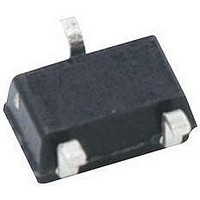
HSMP-389C-TR1 Avago Technologies US Inc., HSMP-389C-TR1 Datasheet - Page 4

HSMP-389C-TR1
Manufacturer Part Number
HSMP-389C-TR1
Description
DIODE PIN SWITCH 100V 1A SOT-323
Manufacturer
Avago Technologies US Inc.
Datasheet
1.HSMP-3892-TR1.pdf
(12 pages)
Specifications of HSMP-389C-TR1
Package / Case
SC-70-3, SOT-323-3
Diode Type
PIN - 1 Pair Series Connection
Voltage - Peak Reverse (max)
100V
Current - Max
1A
Capacitance @ Vr, F
0.3pF @ 5V, 1MHz
Resistance @ If, F
2.5 Ohm @ 5mA, 100MHz
Series Resistance @ If
2.5ohm
Peak Reflow Compatible (260 C)
No
Reel Quantity
3000
Pin Configuration
Series Pair
Leaded Process Compatible
No
Mounting Type
Surface Mount
Breakdown Voltage
100V
Lead Free Status / RoHS Status
Contains lead / RoHS non-compliant
Power Dissipation (max)
-
Lead Free Status / RoHS Status
Contains lead / RoHS non-compliant, Contains lead / RoHS non-compliant
Available stocks
Company
Part Number
Manufacturer
Quantity
Price
Company:
Part Number:
HSMP-389C-TR1
Manufacturer:
AVAGO
Quantity:
8 000
Part Number:
HSMP-389C-TR1
Manufacturer:
AGILENT
Quantity:
20 000
HSMP-389x Series Typical Performance, T
Typical Applications for Multiple Diode Products
0
Figure 6. HSMP-389L used in a SP3T Switch.
Figure 1. Total RF Resistance at 25°C
vs. Forward Bias Current.
100
Figure 4. Typical Reverse Recovery
Time vs. Reverse Voltage.
200
160
120
0.1
10
80
40
0.01
1
0
10
I
F
– FORWARD BIAS CURRENT (mA)
FORWARD CURRENT (mA)
15
0.1
V
V
V
R
R
R
3
4
= –2V
= –5V
= –10V
20
1
2
5
1
6
25
b1
10
100
30
b2
b3
Figure 2. Capacitance vs. Reverse
Voltage.
0.55
0.50
0.45
0.40
0.35
0.30
0.25
0.20
Figure 5. Forward Current vs. Forward
Voltage.
0.01
1
100
0.1
10
1
0
0
2
V
V
R
0.2
F
1 GHz
– REVERSE VOLTAGE (V)
3
4
– FORWARD VOLTAGE (V)
0.4
125°C 25°C –50°C
RF in
8
C
1 MHz
0.6
= 25°C, each diode
12
Figure 7. HSMP-389L Unconnected Trio used in a
Dual Voltage, High Isolation Switch.
0.8
1
16
1.0
1.2
20
3
4
2
2
5
Figure 3. 2nd Harmonic Input
Intercept Point vs. Forward Bias
Current.
4
120
115
110
105
100
95
90
85
1
1
6
Diode Mounted as a
Series Attenuator in a
50 Ohm Microstrip and
Tested at 123 MHz
I
F
– FORWARD BIAS CURRENT (mA)
“ON”
“OFF”
1
0
0
1
10
+V
–V
2
RF out
30


