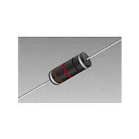
9250A-474-RC Bourns Inc., 9250A-474-RC Datasheet - Page 2

9250A-474-RC
Manufacturer Part Number
9250A-474-RC
Description
Ind Choke Shielded/Molded 470uH 10% 790KHz 60Q-Factor Ferrite 92mA AXL Bag
Manufacturer
Bourns Inc.
Type
Choker
Series
9250Ar
Datasheet
1.9250A-226-RC.pdf
(3 pages)
Specifications of 9250A-474-RC
Product Length
10.92 mm
Lead Style
Axial
Core Material
Ferrite
Inductance
470 uH
Tolerance
10 %
Self Resonant Frequency
5.7MHz
Test Frequency
790KHz
Tolerance (+ Or -)
10%
Impedance
Not RequiredOhm
Lead Spacing
Not Requiredmm
Operating Temp Range
-55C to 125C
Dc Current
92mA
Dc Resistance
9.5Ohm
Quality Factor
60
Military Standard
Not Required
Failure Rate
Not Required
Product Diameter (mm)
4.11mm
Product Height (mm)
Not Requiredmm
Product Depth (mm)
Not Requiredmm
Product Length (mm)
10.41mm
Protection Style
Shielded/Molded
Dimensions
0.16 in Dia. x 0.41 in L
Shielding
Shielded
Maximum Dc Current
92 mAmps
Maximum Dc Resistance
9.5 Ohms
Q Minimum
60
Operating Temperature Range
- 55 C to + 125 C
Termination Style
Axial
Inductance Tolerance
± 10%
Dc Resistance Max
9.5ohm
Dc Current Rating
92mA
Q Factor
60
Inductor Case Style
Axial Leaded
No. Of Pins
2
Lead Free Status / RoHS Status
Compliant
Lead Free Status / RoHS Status
Compliant
Bourns Part No.
9250A-105-RC
9250A-125-RC
9250A-155-RC
9250A-185-RC
9250A-225-RC
9250A-275-RC
9250A-335-RC
9250A-395-RC
9250A-475-RC
9250A-565-RC
9250A-685-RC
9250A-825-RC
9250A-106-RC
9250A-126-RC
9250A-156-RC
9250A-186-RC
9250A-226-RC
9250A-276-RC
9250A-336-RC
9250A-396-RC
9250A-476-RC
9250A-566-RC
9250A-686-RC
9250A-826-RC
9250A-107-RC
Electrical Specifications (Continued)
Product Dimensions
9250A Series Molded Axial Inductor
(0.025)
0.635
(1.00)
25.4
TYP.
100,000
10,000
12,000
15,000
18,000
22,000
27,000
33,000
39,000
47,000
56,000
68,000
82,000
1000
1200
1500
1800
2200
2700
3300
3900
4700
5600
6800
8200
(µH)
Inductance
Tol. (%)
±10
±10
±10
±10
±10
±10
±10
±10
±10
±10
±10
±10
±10
±10
±10
±10
±10
±10
±10
±10
±10
±10
±10
±10
±10
Min.
60
45
45
45
45
45
45
45
45
44
40
40
40
30
30
30
27
27
27
27
23
23
23
21
18
Q
10.41 ± 0.51
(0.41 ± 0.02)
Frequency
(0.162 ± 0.01)
4.11 ± 0.25
(MHz)
0.079
0.079
0.079
0.079
0.079
0.079
0.079
0.079
0.079
0.079
0.079
0.079
Test
0.79
0.25
0.25
0.25
0.25
0.25
0.25
0.25
0.25
0.25
0.25
0.25
0.25
(MHz)
0.97
0.92
0.84
0.74
0.73
0.66
0.54
0.47
0.33
0.29
0.28
0.25
0.21
0.19
0.17
0.16
0.14
0.13
0.12
0.11
SRF
Min.
3.8
1.5
1.2
1.0
0.8
DIMENSIONS:
Max.
DCR
17.5
22.1
26.5
29.9
33.8
47.3
53.0
73.8
81.6
98.9
111
119
137
143
157
175
274
308
343
376
473
512
580
618
678
Ω
(mA)
Idc
70
60
55
50
50
40
40
35
31
28
27
26
24
23
22
21
17
16
15
15
13
13
12
11
11
(INCHES)
Customers should verify actual device performance in their specific applications.
MM
(mA)
Isat
7.5
5.5
3.5
40
35
33
30
27
25
22
20
19
17
16
15
14
13
12
10
9
8
6
5
4
3
Example for L value 10 µH and higher
270 µH, ±5 %
Example for L value less than 10 µH
6.8 µH, ±10 %
Orange
Brown
Yellow
Green
Violet
White
Typ. Part Marking - MIL-STD Color Code
Color
Black
S
Gold
Blue
Gray
Red
v l i
r e
Specifications are subject to change without notice.
Mil. identifi er (Silver, twice the width
of other bands)
1st signifi cant fi gure (Blue)
Decimal point (Gold)
2nd signifi cant fi gure (Gray)
Tolerance (Silver)
Mil. identifi er (Silver, twice the width
of other bands)
1st signifi cant fi gure (Red)
2nd signifi cant fi gure (Purple)
Multiplier (Brown)
Tolerance (Gold)
Signifi cant Figure
or Decimal Point
Decimal Point
1st & 2nd
1
3
4
5
6
7
9
0
2
8
Multiplier
1000
100
10
1
Tolerance
±
± 5 %
0 1
%


