26MT120 Vishay, 26MT120 Datasheet - Page 3
26MT120
Manufacturer Part Number
26MT120
Description
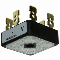
Diode Rectifier Bridge Single 1.2KV 25A 5-Pin D-63
Manufacturer
Vishay
Specifications of 26MT120
Package
5D-63
Peak Average Forward Current
25 A
Peak Forward Voltage
1.26@40A V
Peak Reverse Current
200 uA
Peak Reverse Repetitive Voltage
1200 V
Bridge Type
Three Phase
Configuration
Single
Voltage - Peak Reverse (max)
1200V
Current - Dc Forward (if)
25A
Diode Type
Three Phase
Speed
Standard Recovery >500ns, > 200mA (Io)
Mounting Type
QC Terminal
Package / Case
D-63
Product
Three Phase Bridge
Peak Reverse Voltage
1200 V
Max Surge Current
375 A
Forward Voltage Drop
1.26 V
Maximum Reverse Leakage Current
200 uA
Maximum Operating Temperature
+ 150 C
Length
28.5 mm
Width
28.5 mm
Height
10 mm
Mounting Style
Stud
Minimum Operating Temperature
- 55 C
No. Of Phases
Three
Repetitive Reverse Voltage Vrrm Max
1.2kV
Forward Current If(av)
25A
Forward Voltage Vf Max
1.26V
Operating Temperature Range
-55°C To +150°C
Lead Free Status / RoHS Status
Lead free / RoHS Compliant
Reverse Recovery Time (trr)
-
Lead Free Status / Rohs Status
Lead free / RoHS Compliant
Other names
*26MT120
VS-26MT120
VS-26MT120
VS26MT120
VS26MT120
VS-26MT120
VS-26MT120
VS26MT120
VS26MT120
Available stocks
Company
Part Number
Manufacturer
Quantity
Price

Part Number:
26MT120
Manufacturer:
IR
Quantity:
20 000


Document Number: 93565
Revision: 03-Nov-08
320
300
280
260
240
220
200
180
160
140
120
100
160
140
120
100
55
50
45
40
35
30
25
20
15
10
80
80
60
5
0
Fig. 4 - Maximum Non-Repetitive Surge Current
1
0
0
Number of Equal Amplitude Half Cycle
26MT.. Series
26MT.. Series
T
Fig. 1 - Current Ratings Characteristics
J
~
= 150 °C
5
Total Output Current (A)
Total Output Current (A)
5
At any rated load condition and with
rated V
Current Pulses (N)
10
120° (rect.)
RRM
+
-
10
15
10
applied following surge.
For technical questions, contact: ind-modules@vishay.com
Initial T
26MT.. Series
at 60 Hz 0.0083 s
at 50 Hz 0.0100 s
20
(Power Modules), 25/35 A
20
120° (rect.)
J
= 150 °C
25
Three Phase Bridge
Fig. 3 - Total Power Loss Characteristics
100
30
25
1000
400
360
320
280
240
200
160
120
100
80
55
50
45
40
35
30
25
20
15
10
10
Maximum Allowable Ambient Temperature (°C)
5
0
1
Fig. 5 - Maximum Non-Repetitive Surge Current
0.01
0
0
Fig. 2 - Forward Voltage Drop Characteristics
Vishay High Power Products
26MT.. Series
26MT.. Series
Instantaneous Forward Voltage (V)
0.5
25
26MT../36MT.. Series
Pulse Drain Duration (s)
1.0
Maximum non-repetitive surge current
versus pulse train duration.
50
1.5
T
T
J
J
= 25 °C
= 150 °C
Per junction
2.0
0.1
75
Initial T
No voltage reapplied
Rated V
2.5
100
J
RRM
3.0
= 150 °C
www.vishay.com
125
reapplied
3.5
150
4.0
1
3
Related parts for 26MT120
Image
Part Number
Description
Manufacturer
Datasheet
Request
R

Part Number:
Description:
357-036-542-201 CARDEDGE 36POS DL .156 BLK LOPRO
Manufacturer:
Vishay
Datasheet:
Part Number:
Description:
357-036-542-201 CARDEDGE 36POS DL .156 BLK LOPRO
Manufacturer:
Vishay
Datasheet:
Part Number:
Description:
357-036-542-201 CARDEDGE 36POS DL .156 BLK LOPRO
Manufacturer:
Vishay
Datasheet:
Part Number:
Description:
357-036-542-201 CARDEDGE 36POS DL .156 BLK LOPRO
Manufacturer:
Vishay
Datasheet:
Part Number:
Description:
357-036-542-201 CARDEDGE 36POS DL .156 BLK LOPRO
Manufacturer:
Vishay
Datasheet:
Part Number:
Description:
357-036-542-201 CARDEDGE 36POS DL .156 BLK LOPRO
Manufacturer:
Vishay
Datasheet:
Part Number:
Description:
357-036-542-201 CARDEDGE 36POS DL .156 BLK LOPRO
Manufacturer:
Vishay
Datasheet:
Part Number:
Description:
357-036-542-201 CARDEDGE 36POS DL .156 BLK LOPRO
Manufacturer:
Vishay
Datasheet:
Part Number:
Description:
357-036-542-201 CARDEDGE 36POS DL .156 BLK LOPRO
Manufacturer:
Vishay
Datasheet:
Part Number:
Description:
357-036-542-201 CARDEDGE 36POS DL .156 BLK LOPRO
Manufacturer:
Vishay
Datasheet:
Part Number:
Description:
357-036-542-201 CARDEDGE 36POS DL .156 BLK LOPRO
Manufacturer:
Vishay
Datasheet:
Part Number:
Description:
357-036-542-201 CARDEDGE 36POS DL .156 BLK LOPRO
Manufacturer:
Vishay
Datasheet:
Part Number:
Description:
357-036-542-201 CARDEDGE 36POS DL .156 BLK LOPRO
Manufacturer:
Vishay
Datasheet:
Part Number:
Description:
357-036-542-201 CARDEDGE 36POS DL .156 BLK LOPRO
Manufacturer:
Vishay
Datasheet:
Part Number:
Description:
357-036-542-201 CARDEDGE 36POS DL .156 BLK LOPRO
Manufacturer:
Vishay
Datasheet: