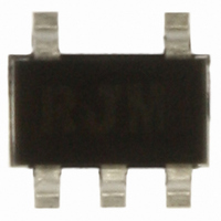
SMP1307-027LF Skyworks Solutions Inc, SMP1307-027LF Datasheet - Page 2

SMP1307-027LF
Manufacturer Part Number
SMP1307-027LF
Description
DIODE PIN 200V 250MW SOT-5
Manufacturer
Skyworks Solutions Inc
Datasheet
1.SMP1307-011LF.pdf
(9 pages)
Specifications of SMP1307-027LF
Diode Type
PIN - 2 Pair CA + CC
Voltage - Peak Reverse (max)
200V
Capacitance @ Vr, F
0.3pF @ 30V, 1MHz
Resistance @ If, F
3 Ohm @ 100mA, 100MHz
Power Dissipation (max)
250mW
Package / Case
SOT-5
Lead Free Status / RoHS Status
Lead free / RoHS Compliant
Current - Max
-
Other names
863-1091-2
Available stocks
Company
Part Number
Manufacturer
Quantity
Price
Part Number:
SMP1307-027LF
Manufacturer:
FREESCALE
Quantity:
20 000
DATA SHEET • SMP1307 SERIES
Table 1. SMP1307 Series Packaging and Marking
SMP1307-027 Four-Diode PI Attenuator
The SMP1307-027 uses four PIN diode junctions in a five-lead
SOT package. It is configured for ease of insertion in the PI
attenuator circuit commonly used for broadband TV distribution
systems, covering a frequency range from 5 MHz to over 1 GHz.
A broadband attenuator was designed using the SMP1307-027
that shows good performance up to 2 GHz. The attenuator was
evaluated with a 50 Ω source and load impedance. Figure 1
shows a block diagram and circuit diagram for this device (the
typical performance of the SMP1307-027 is shown in Figure 2).
2
♦SMP1307-001LF
♦SMP1307-001
Marking: PJ1
Marking: RJ1
L
S
Green™
SOT-23
Single
= 1.5 nH
The Pb-free symbol or “LF” in the part number denotes a lead-free, RoHS-compliant package unless otherwise noted as Green™. Tin/lead (Sn/Pb) packaging is not recommended
Innovation to Go™
for new designs.
Select Linear Products (indicated by ♦) now available for purchase online.
Skyworks Solutions, Inc. • Phone [781] 376-3000 • Fax [781] 376-3100 • sales@skyworksinc.com • www.skyworksinc.com
November 11, 2010 • Skyworks Proprietary Information • Products and Product Information are Subject to Change Without Notice • 200045H
RF Input
SMP1307-003LF
Common Anode
Marking:RJ9
L
S
Green™
SOT-23
= 1.5 nH
10000 pF
C1
560 Ω
Figure 1. SMP1307-027 Block Diagram and Schematic
Common Cathode
SMP1307-004LF
R1
SMP1307-004
Marking: PJ3
Marking: RJ3
L
S
SOT-23
= 1.5 nH
10000 pF
C2
D2
3
4
10000 pF
SMP1307-005LF
1 kΩ
SMP1307-005
560 Ω
R3
D1
Marking: RJ2
Marking: PJ2
L
Series Pair
C3
2
S
Green™
R5
1 kΩ
SOT-23
= 1.5 nH
R2
1
5
Electrical and Mechanical Specifications
The absolute maximum ratings of the SMP1307 series are
provided in Table 2. Electrical specifications are provided in
Table 3. Resistance versus temperature measurements are
provided in Table 4.
Typical performance characteristics of the SMP1307 series are
illustrated in Figures 2 to 6. Package dimensions are shown in
Figures 7 to 11 (odd numbers), and tape and reel dimensions are
provided in Figures 8 to 12 (even numbers).
1 kΩ
R4
D3
10000 pF
D4
Reverse Series Pair
SMP1307-006LF
C6
Marking: RJ8
L
C4
10000 pF
S
Green™
SOT-23
= 1.5 nH
560 Ω
R6
V
REF
V
(5 V)
10000 pF
TUNE
C5
(0 - 20 V)
SMP1307-011LF
Marking: RJ
L
SOD-323
S
Green™
Single
= 1.5 nH
RF Output
S1658
SMP1307-027LF
SMP1307-027
Marking: RJM
Marking: PJM
Green™
SOT-5
PI


