12061A820JAT2A AVX Corporation, 12061A820JAT2A Datasheet - Page 7
12061A820JAT2A
Manufacturer Part Number
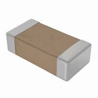
12061A820JAT2A
Description
Cap Ceramic 82pF 100VDC C0G 5% SMD 1206 Paper T/R
Manufacturer
AVX Corporation
Type
Flatr
Series
C0G (NPO) Dielectricr
Specifications of 12061A820JAT2A
Package/case
1206
Mounting
Surface Mount
Capacitance Value
82 pF
Dielectric
C0G
Voltage
100 Vdc
Product Length
3.2 mm
Product Height
0.94(Max) mm
Product Depth
1.6 mm
Tolerance
5 %
Capacitance
82pF
Voltage - Rated
100V
Temperature Coefficient
C0G, NP0
Mounting Type
Surface Mount, MLCC
Operating Temperature
-55°C ~ 125°C
Applications
General Purpose
Package / Case
1206 (3216 Metric)
Size / Dimension
0.126" L x 0.063" W (3.20mm x 1.60mm)
Thickness
0.94mm Max
Dielectric Characteristic
C0G / NP0
Capacitance Tolerance
± 5%
Voltage Rating
100VDC
Capacitor Case Style
1206
No. Of Pins
2
Capacitor Mounting
SMD
Rohs Compliant
Yes
Brand/series
1206 Series
Case Size
1206
Dielectric Strength
No breakdown or visual defects
Insulation Resistance
100000 Megohms
Length
0.126 in. ±0.008 in.
Material, Element
Ceramic
Package Type
Paper⁄Embossed (7 in. Reel)
Temperature, Operating, Maximum
125 °C
Temperature, Operating, Minimum
-55 °C
Termination
SMT
Voltage, Rating
100 VDC
Width
0.063 in. ±0.008 in.
Operating Temperature Range
- 55 C to + 125 C
Temperature Coefficient / Code
C0G (NP0)
Product
General Type MLCCs
Dimensions
1.6 mm W x 3.2 mm L x 0.5 mm H
Termination Style
SMD/SMT
Lead Free Status / RoHS Status
Lead free / RoHS Compliant
Features
-
Ratings
-
Lead Spacing
-
Lead Free Status / Rohs Status
RoHS Compliant part
Other names
12061A820JAT2A
478-5042-2
478-5042-2


Paper Carrier Configuration
8 & 12mm Tape Only
8 & 12mm Paper Tape
Metric Dimensions Will Govern
Bar Code Labeling Standard
AVX bar code labeling is available and follows latest version of EIA-556
CONSTANT DIMENSIONS
VARIABLE DIMENSIONS
NOTES:
1. The cavity defined by A
62
Tape Size
surrounding the component so that:
Tape Size
12mm
8mm
1/2 Pitch
a) the component does not protrude beyond either surface of the carrier tape;
b) the component can be removed from the cavity in a vertical direction without
c) rotation of the component is limited to 20º maximum (see Sketches A & B);
d) lateral movement of the component is restricted to 0.5mm maximum
and
Double
12mm
12mm
mechanical restriction after the top cover tape has been removed;
(see Sketch C).
8mm
8mm
Pitch
0
(0.059
, B
(0.157 ± 0.004)
(0.157 ± 0.004)
(0.079 ± 0.002)
(0.315 ± 0.004)
BOTTOM
1.50
0
, and T shall be configured to provide sufficient clearance
COVER
4.00 ± 0.010
See Note 4
4.00 ± 0.10
2.00 ± 0.05
8.00 ± 0.10
TAPE
D
0
+0.004
-0.0
+0.10
-0.0
P
1
)
(0.069 ± 0.004) (0.157 ± 0.004) (0.079 ± 0.002)
1.75 ± 0.10
T
T
1
T
COVER
1
TAPE
TOP
E
E
(0.246)
(0.404)
(0.246)
(0.404)
10.25
10.25
2
6.25
6.25
CAVITY SIZE
SEE NOTE 1
Min.
0.50mm (0.020)
Maximum
4.00 ± 0.10
Top View, Sketch "C"
Component Lateral
P
0
(0.138 ± 0.002)
(0.217 ± 0.002)
(0.138 ± 0.002)
(0.217 ± 0.002)
D
3.50 ± 0.05
5.50 ± 0.05
3.50 ± 0.05
5.50 ± 0.05
0
CENTER LINES
OF CAVITY
A
0.50mm (0.020)
0
F
2. Tape with or without components shall pass around radius “R” without damage.
3. Bar code labeling (if required) shall be on the side of the reel opposite the sprocket
4. If P
Maximum
B
2.00 ± 0.05
holes. Refer to EIA-556.
0
P
1
2
= 2.0mm, the tape may not properly index in all tape feeders.
P
P
2
0
(0.472 ± 0.012)
(0.472 ± 0.012)
P
12.0 ± 0.30
12.0 ± 0.30
(0.315
(0.315
User Direction of Feed
1
8.00
8.00
10 PITCHES CUMULATIVE
TOLERANCE ON TAPE
±0.20mm (±0.008)
W
+0.012
-0.004
+0.012
-0.004
+0.30
-0.10
+0.30
-0.10
(0.004)
Max.
0.10
T
)
)
E
G
1
F
1
E
2
W
See Note 1
A
0
G. Min.
(0.030)
B
0.75
Min.
0
Base Compositions
for Paper Base
for Non-Paper
(0.043) Max.
(0.063) Max.
25.0 (0.984)
See Note 2
Tape and
1.10mm
1.60mm
R Min.
Min.
T
Related parts for 12061A820JAT2A
Image
Part Number
Description
Manufacturer
Datasheet
Request
R

Part Number:
Description:
Manufacturer:
AVX Corporation
Datasheet:
Part Number:
Description:
Manufacturer:
AVX Corporation
Datasheet:
Part Number:
Description:
Manufacturer:
AVX Corporation
Datasheet:
Part Number:
Description:
Manufacturer:
AVX Corporation
Datasheet:
Part Number:
Description:
Manufacturer:
AVX Corporation
Datasheet: