NTD20P06LG ON Semiconductor, NTD20P06LG Datasheet - Page 7
NTD20P06LG
Manufacturer Part Number
NTD20P06LG
Description
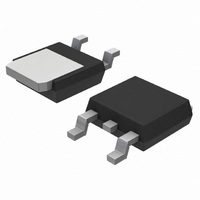
MOSFET P-CH 60V 15.5A DPAK
Manufacturer
ON Semiconductor
Type
Power MOSFETr
Specifications of NTD20P06LG
Fet Type
MOSFET P-Channel, Metal Oxide
Fet Feature
Logic Level Gate
Rds On (max) @ Id, Vgs
150 mOhm @ 7.5A, 5V
Drain To Source Voltage (vdss)
60V
Current - Continuous Drain (id) @ 25° C
15.5A
Vgs(th) (max) @ Id
2V @ 250µA
Gate Charge (qg) @ Vgs
26nC @ 5V
Input Capacitance (ciss) @ Vds
1190pF @ 25V
Power - Max
65W
Mounting Type
Surface Mount
Package / Case
DPak, TO-252 (2 leads+tab), SC-63
Configuration
Single
Transistor Polarity
P-Channel
Resistance Drain-source Rds (on)
0.13 Ohms
Forward Transconductance Gfs (max / Min)
17.5 S
Drain-source Breakdown Voltage
- 60 V
Gate-source Breakdown Voltage
+/- 20 V
Continuous Drain Current
- 15.5 A
Power Dissipation
65 W
Maximum Operating Temperature
+ 175 C
Mounting Style
SMD/SMT
Minimum Operating Temperature
- 55 C
Number Of Elements
1
Polarity
P
Channel Mode
Enhancement
Drain-source On-res
0.15Ohm
Drain-source On-volt
60V
Gate-source Voltage (max)
±20V
Output Power (max)
Not RequiredW
Frequency (max)
Not RequiredMHz
Noise Figure
Not RequireddB
Power Gain
Not RequireddB
Drain Efficiency
Not Required%
Operating Temp Range
-55C to 175C
Operating Temperature Classification
Military
Mounting
Surface Mount
Pin Count
2 +Tab
Package Type
DPAK
Lead Free Status / RoHS Status
Lead free / RoHS Compliant
Other names
NTD20P06LG
NTD20P06LGOS
NTD20P06LGOS
Available stocks
Company
Part Number
Manufacturer
Quantity
Price
Company:

Part Number:
NTD20P06LG
Manufacturer:
ON
Quantity:
872
Company:
Part Number:
NTD20P06LG
Manufacturer:
ON
Quantity:
12 500
Company:
Part Number:
NTD20P06LG
Manufacturer:
ON
Quantity:
12 500


L3
L4
b2
e
1
b3
4
2
E
3
b
A
D
0.005 (0.13)
B
*For additional information on our Pb−Free strategy and soldering
details, please download the ON Semiconductor Soldering and
Mounting Techniques Reference Manual, SOLDERRM/D.
M
DETAIL A
C
0.228
5.80
c
L2
A
GAUGE
PLANE
PACKAGE DIMENSIONS
DPAK (SINGLE GAUGE)
SOLDERING FOOTPRINT*
ROTATED 90 CW
0.244
c2
DETAIL A
H
6.20
C
http://onsemi.com
L
CASE 369C−01
L1
ISSUE D
5
0.102
2.58
7
A1
0.118
3.00
H
0.063
1.60
SCALE 3:1
C
Z
SEATING
PLANE
0.243
6.17
NOTES:
inches
mm
1. DIMENSIONING AND TOLERANCING PER ASME
2. CONTROLLING DIMENSION: INCHES.
3. THERMAL PAD CONTOUR OPTIONAL WITHIN DI-
4. DIMENSIONS D AND E DO NOT INCLUDE MOLD
5. DIMENSIONS D AND E ARE DETERMINED AT THE
6. DATUMS A AND B ARE DETERMINED AT DATUM
Y14.5M, 1994.
MENSIONS b3, L3 and Z.
FLASH, PROTRUSIONS, OR BURRS. MOLD
FLASH, PROTRUSIONS, OR GATE BURRS SHALL
NOT EXCEED 0.006 INCHES PER SIDE.
OUTERMOST EXTREMES OF THE PLASTIC BODY.
PLANE H.
STYLE 2:
DIM
A1
b2
b3
L1
L2
L3
L4
PIN 1. GATE
c2
A
b
c
D
E
e
H
L
Z
2. DRAIN
3. SOURCE
4. DRAIN
0.086
0.000
0.025
0.030
0.180
0.018
0.018
0.235
0.250
0.370
0.055
0.035
0.155
MIN
−−−
0.090 BSC
0.108 REF
0.020 BSC
INCHES
0.094
0.005
0.035
0.045
0.215
0.024
0.024
0.245
0.265
0.410
0.070
0.050
0.040
MAX
−−−
MILLIMETERS
MIN
2.18
0.00
0.63
0.76
4.57
0.46
0.46
5.97
6.35
9.40
1.40
0.89
3.93
−−−
2.29 BSC
2.74 REF
0.51 BSC
10.41
MAX
2.38
0.13
0.89
1.14
5.46
0.61
0.61
6.22
6.73
1.78
1.27
1.01
−−−
Related parts for NTD20P06LG
Image
Part Number
Description
Manufacturer
Datasheet
Request
R

Part Number:
Description:
ON Semiconductor [VOLTAGE REGULATOR]
Manufacturer:
ON Semiconductor
Datasheet:
Part Number:
Description:
357-036-542-201 CARDEDGE 36POS DL .156 BLK LOPRO
Manufacturer:
ON Semiconductor
Datasheet:
Part Number:
Description:
357-036-542-201 CARDEDGE 36POS DL .156 BLK LOPRO
Manufacturer:
ON Semiconductor
Datasheet:
Part Number:
Description:
357-036-542-201 CARDEDGE 36POS DL .156 BLK LOPRO
Manufacturer:
ON Semiconductor
Datasheet:
Part Number:
Description:
357-036-542-201 CARDEDGE 36POS DL .156 BLK LOPRO
Manufacturer:
ON Semiconductor
Datasheet:
Part Number:
Description:
357-036-542-201 CARDEDGE 36POS DL .156 BLK LOPRO
Manufacturer:
ON Semiconductor
Datasheet:
Part Number:
Description:
357-036-542-201 CARDEDGE 36POS DL .156 BLK LOPRO
Manufacturer:
ON Semiconductor
Datasheet:
Part Number:
Description:
357-036-542-201 CARDEDGE 36POS DL .156 BLK LOPRO
Manufacturer:
ON Semiconductor
Datasheet:
Part Number:
Description:
357-036-542-201 CARDEDGE 36POS DL .156 BLK LOPRO
Manufacturer:
ON Semiconductor
Datasheet:
Part Number:
Description:
357-036-542-201 CARDEDGE 36POS DL .156 BLK LOPRO
Manufacturer:
ON Semiconductor
Datasheet:
Part Number:
Description:
357-036-542-201 CARDEDGE 36POS DL .156 BLK LOPRO
Manufacturer:
ON Semiconductor
Datasheet:
Part Number:
Description:
Manufacturer:
ON Semiconductor
Datasheet:
Part Number:
Description:
Manufacturer:
ON Semiconductor
Datasheet:
Part Number:
Description:
Manufacturer:
ON Semiconductor
Datasheet: