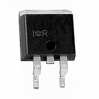
IRL1004SPBF International Rectifier, IRL1004SPBF Datasheet - Page 5

IRL1004SPBF
Manufacturer Part Number
IRL1004SPBF
Description
MOSFET N-CH 40V 130A D2PAK
Manufacturer
International Rectifier
Series
HEXFET®r
Specifications of IRL1004SPBF
Fet Type
MOSFET N-Channel, Metal Oxide
Fet Feature
Logic Level Gate
Rds On (max) @ Id, Vgs
6.5 mOhm @ 78A, 10V
Drain To Source Voltage (vdss)
40V
Current - Continuous Drain (id) @ 25° C
130A
Vgs(th) (max) @ Id
1V @ 250µA
Gate Charge (qg) @ Vgs
100nC @ 4.5V
Input Capacitance (ciss) @ Vds
5330pF @ 25V
Power - Max
3.8W
Mounting Type
Surface Mount
Package / Case
D²Pak, TO-263 (2 leads + tab)
Current, Drain
130 A
Gate Charge, Total
100 nC
Package Type
D2Pak
Polarization
N-Channel
Power Dissipation
200 W
Resistance, Drain To Source On
0.0065 Ohm
Temperature, Operating, Maximum
+175 °C
Temperature, Operating, Minimum
-55 °C
Time, Turn-off Delay
25 ns
Time, Turn-on Delay
16 ns
Transconductance, Forward
63 S
Voltage, Breakdown, Drain To Source
40 V
Voltage, Forward, Diode
1.3 V
Voltage, Gate To Source
±16 V
Transistor Polarity
N Channel
Continuous Drain Current Id
110A
Drain Source Voltage Vds
40V
On Resistance Rds(on)
6.5mohm
Rds(on) Test Voltage Vgs
10V
Threshold Voltage Vgs Typ
1V
Rohs Compliant
Yes
Lead Free Status / RoHS Status
Lead free / RoHS Compliant
Other names
*IRL1004SPBF
www.irf.com
140
120
100
0.01
0.1
80
60
40
20
0.00001
0
1
Fig 9. Maximum Drain Current Vs.
25
D = 0.50
Fig 11. Maximum Effective Transient Thermal Impedance, Junction-to-Case
0.20
0.10
0.05
0.02
0.01
50
Case Temperature
T , Case Temperature ( C)
C
LIMITED BY PACKAGE
75
(THERMAL RESPONSE)
0.0001
SINGLE PULSE
100
125
t , Rectangular Pulse Duration (sec)
°
1
150
0.001
175
Fig 10b. Switching Time Waveforms
Fig 10a. Switching Time Test Circuit
V
90%
10%
V
DS
GS
0.01
t
d(on)
1. Duty factor D = t / t
2. Peak T = P
Notes:
t
r
J
≤ 0.1 %
≤ 1
DM
x Z
1
0.1
thJC
P
2
DM
+ T
t
d(off)
C
t
1
t
t
2
f
+
-
1
5


