6140 Cinch Connectors, 6140 Datasheet - Page 166
6140
Manufacturer Part Number
6140
Description
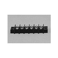
Terminal Block,12 Contacts,0.375 Pitch
Manufacturer
Cinch Connectors
Type
Barrier Stripr
Datasheet
1.6140.pdf
(282 pages)
Specifications of 6140
Number Of Contacts
6POS
Number Of Contact Rows
2
Termination Method
Screw
Mounting Style
Panel
Contact Pitch (mm)
9.53mm
Current Rating (max)
15A
Operating Temp Range
-48C to 148C
Housing Material
Phenolic
Body Orientation
Straight
Operating Voltage (max)
250VAC
Product Height (mm)
28.58mm
Product Length (mm)
73.83mm
Wire Gauge
16
Lead Free Status / RoHS Status
Compliant
Available stocks
Company
Part Number
Manufacturer
Quantity
Price
Company:

Part Number:
6140-1004
Manufacturer:
SUMITOMO
Quantity:
50 000
Company:
Part Number:
61400-1
Manufacturer:
TE
Quantity:
20 000
Company:
Part Number:
61400-1
Manufacturer:
DELPHI
Quantity:
35 000
Company:
Part Number:
61400413321
Manufacturer:
WE
Quantity:
12 000
Company:
Part Number:
61400416021
Manufacturer:
WE
Quantity:
12 000
Part Number:
61407-3
Manufacturer:
TE/泰科
Quantity:
20 000


D-subminiature Metal Shell
MIL-C-24308
M24308 Series
Insulator Material: Glass-filled diallyl phthalate (green)
Connector Shell: Steel with cadmium plating and yellow
Contact Material: Plug - Brass (machined), Socket - Phosphor
Contact Plating: 50µin. gold over copper or nickel
Dual Float Bushing: Stainless steel, passivated or
Operating Temperature: -65°C to + 125°C
Shock: 50G peak per MIL-STD-202, Method 213, Condition G
Vibration: 12 cycles in three perpendicular directions @
Moisture Resistance: 90-95% relative humidity @ 40°C for 96
Individual Contact Insertion and
Durability: 500 mating cycles
Call Toll Free: 1 (800) 323-9612
Insulation Resistance:
Separation Force (minimum/maximum): 0.7 oz./12 oz.
Withstanding Voltage:
Meets all MIL-C-24308 Class G specifications.
Offered in Crimp and Poke and Solder Cup and PCB vertical and right-angle.
Offered in 9, 15, 25, 37, and 50 position plugs and sockets except right-angle (9 to 37 positions).
Monoblock green diallyl phthalate insulator for improved electrical performance.
See pages 4-5 thru 4-10 for standard dimensions, contact arrangements, and panel
mounting specifications.
Contact Resistance:
Current Rating:
10-2000Hz, per MIL-STD-202 Method 204,
Condition D
chromate finish
bronze (machined)
per MIL-M-14, Type SDG-F
non-magnetic brass
hours per MIL-STD-202, Method 103
Minimum 1250V RMS @ sea level
5 Amps
2.7 milliohms maximum
5000 megohms maximum (initial);
1000 megohms (minimum) after
environmental testing
4-74
Related parts for 6140
Image
Part Number
Description
Manufacturer
Datasheet
Request
R

Part Number:
Description:
Standard Card Edge Connectors CINCH BLK CARD GUIDE
Manufacturer:
Cinch Connectors

Part Number:
Description:
TERMINAL BLOCK JUMPER TYPE F
Manufacturer:
Cinch Connectors
Datasheet:
Part Number:
Description:
D-Subminiature Connectors MCHNED PIN 20-24AWG
Manufacturer:
Cinch Connectors
Datasheet:
Part Number:
Description:
Terminal Block,4 Contacts,0.44 Pitch
Manufacturer:
Cinch Connectors
Datasheet:

Part Number:
Description:
Terminal Block,8 Contacts,0.375 Pitch
Manufacturer:
Cinch Connectors
Datasheet: