IRF6665 International Rectifier, IRF6665 Datasheet
IRF6665
Specifications of IRF6665
Available stocks


Related parts for IRF6665

IRF6665 Summary of contents
Page 1
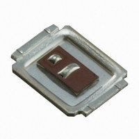
... Class-D audio amplifier performance factors such as efficiency, THD, and EMI. The IRF6665 device utilizes DirectFET TM packaging technology. DirectFET TM packaging technology offers lower parasitic inductance and resistance when compared to conventional wirebonded SOIC packaging. Lower inductance improves EMI performance by reducing the voltage ringing that accompanies fast current transients ...
Page 2
... IRF6665 Static @ T = 25°C (unless otherwise specified) J Parameter V Drain-to-Source Breakdown Voltage (BR)DSS ∆V /∆T Breakdown Voltage Temp. Coefficient (BR)DSS J R Static Drain-to-Source On-Resistance DS(on) V Gate Threshold Voltage GS(th) I Drain-to-Source Leakage Current DSS I Gate-to-Source Forward Leakage GSS Gate-to-Source Reverse Leakage R Internal Gate Resistance ...
Page 3
... TOP 15V 10V 9.0V 8.0V 7.0V BOTTOM 6.0V 100 1000 10 12 Fig 4. Normalized On-Resistance vs. Temperature 100 Fig 6. Typical Gate Charge vs.Gate-to-Source Voltage IRF6665 100 TOP BOTTOM 10 6.0V 1 ≤ 60µs PULSE WIDTH Tj = 150°C 0.1 0 100 Drain-to-Source Voltage (V) Fig 2. Typical Output Characteristics 2 ...
Page 4
... IRF6665 100 -40° 25° 150°C 1 0.4 0.6 0.8 1.0 1 Source-to-Drain Voltage (V) Fig 7. Typical Source-Drain Diode Forward Voltage 100 Ambient Temperature (°C) Fig 9. Maximum Drain Current vs. Ambient Temperature 100 D = 0.50 0.20 10 0.10 0.05 0.02 1 0.01 0.1 SINGLE PULSE ( THERMAL RESPONSE ) 0.01 ...
Page 5
... Fig 15a. Unclamped Inductive Test Circuit V (BR)DSS Fig 15b. Unclamped Inductive Waveforms ≤ 1 ≤ 0.1 % Fig 16a. Switching Time Test Circuit www.irf.com 5. DRIVER + Fig 14. Maximum Avalanche Energy vs. Drain Current 90 IRF6665 120 125°C 100 25° Drain Current (A) Fig 13. On-Resistance vs. Drain Current 50 TOP 40 BOTTOM 5. ...
Page 6
... IRF6665 Current Regulator Same Type as D.U.T. 50KΩ .2µF 12V .3µ D.U. 3mA Current Sampling Resistors Fig 17a. Gate Charge Test Circuit + ‚ - Driver Gate Drive D.U.T. I Reverse Recovery Current D.U.T. V Re-Applied Voltage Inductor Curent Fig 18. 6 Vds Vgs(th) Qgs1 Qgs2 Fig 17b ...
Page 7
... DirectFET™ Substrate and PCB Layout, SH Outline (Small Size Can, H-Designation). Please see DirectFET application note AN-1035 for all details regarding PCB assembly using DirectFET. This includes all recommendations for stencil and substrate designs. www.irf.com IRF6665 7 ...
Page 8
... IRF6665 ™ Please see DirectFET application note AN-1035 for all details regarding PCB assembly using DirectFET. This includes all recommendations for stencil and substrate designs. Note: Controlling dimensions are in mm. ™ 8 DIMENSIONS METRIC IMPERIAL MAX MIN CODE MIN MAX 4.85 A 0.187 4 ...
Page 9
... DirectFET™ Tape & Reel Dimension (Showing component orientation). NOTE: Controlling dimensions in mm Std reel quantity is 4800 parts. (ordered as IRF6665). For 1000 parts on 7" reel, order IRF6665TR1 CODE WORLD HEADQUARTERS: 233 Kansas St., El Segundo, California 90245, USA Tel: (310) 252-7105 www.irf.com ...
Page 10
Note: For the most current drawings please refer to the IR website at: http://www.irf.com/package/ ...