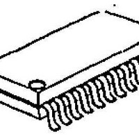
NJM2214M NJR, NJM2214M Datasheet

NJM2214M
Specifications of NJM2214M
Related parts for NJM2214M
NJM2214M Summary of contents
Page 1
... Operating Voltage ● Internal 8 Color Generating Circuit. ● Package Outline ● Bipolar Technology ■ RECOMMENDED OPERATING CONDITION ● Operating Voltage ■ APPLICATION ● VCR, Video Camera Ver.2004-02-17 VIDEO ON-SCREEN DISPLAY (+4.7V to +5.3V) SDIP22, DMP24 4.7 to 5.3V ■ PACKAGE OUTLINE NJM2214L NJM2214M - 1 - ...
Page 2
ABSOLUTE MAXIMUM RATINGS PARAMETER Supply Voltage Power Dissipation Operating Temperature Range Storage Temperature Range ■ ELECTRICAL CHARACTERISTICS PARAMETER SYMBOL Operating Curret I Video Switch Voltage Gain G Frequency Characteristics G Differential Gain DG Differential Phase DP 8 Color Output ...
Page 3
ELECTRICAL CHARACTERISTICS PARAMETER SYMBOL Amplitude C Green Luminance C Phase C Amplitude C Magenta Luminance C Phase C Amplitude C Red Luminance C Phase C Amplitude C Blue Luminance C Phase C Amplitude C Black Luminance C Phase C ...
Page 4
RELATION BETWEEN 8 COLOR OUTPUT AND MATRIX INPUT COLOR MATRIX 1 White L Yellow H Cyan L Green H Magenta L Red H Blue L Black H L=0V (DC) H=5V (DC) ■ CONTROL SIGNAL AND FUNCTION 15 PIN 10 ...
Page 5
TEST CIRCUIT ■ TYPICAL APPLICATION Ver.2004-02- ...
Page 6
APPLICATION This IC requires 1MΩ resistance between INPUT and GND pin for clamp type input since the minute current causes an unstable pin voltage [CAUTION] The specifications on this databook are only given for information , ...


