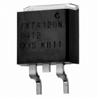
IXTA120N04T2 IXYS, IXTA120N04T2 Datasheet - Page 5

IXTA120N04T2
Manufacturer Part Number
IXTA120N04T2
Description
MOSFET N-CH 40V 120A TO-263
Manufacturer
IXYS
Series
TrenchT2™r
Datasheet
1.IXTP120N04T2.pdf
(6 pages)
Specifications of IXTA120N04T2
Fet Type
MOSFET N-Channel, Metal Oxide
Fet Feature
Standard
Rds On (max) @ Id, Vgs
6.1 mOhm @ 25A, 10V
Drain To Source Voltage (vdss)
40V
Current - Continuous Drain (id) @ 25° C
120A
Vgs(th) (max) @ Id
4V @ 250µA
Gate Charge (qg) @ Vgs
58nC @ 10V
Input Capacitance (ciss) @ Vds
3240pF @ 25V
Power - Max
200W
Mounting Type
Surface Mount
Package / Case
D²Pak, TO-263 (2 leads + tab)
Configuration
Single
Transistor Polarity
N-Channel
Resistance Drain-source Rds (on)
0.0061 Ohms
Drain-source Breakdown Voltage
40 V
Gate-source Breakdown Voltage
+/- 20 V
Continuous Drain Current
120 A
Power Dissipation
200 W
Maximum Operating Temperature
+ 175 C
Mounting Style
SMD/SMT
Minimum Operating Temperature
- 55 C
Vdss, Max, (v)
40
Id(cont), Tc=25°c, (a)
120
Rds(on), Max, Tj=25°c, (?)
0.0061
Ciss, Typ, (pf)
3240
Qg, Typ, (nc)
58
Trr, Typ, (ns)
35
Pd, (w)
200
Rthjc, Max, (k/w)
0.75
Package Style
TO-263
Lead Free Status / RoHS Status
Lead free / RoHS Compliant
© 2008 IXYS CORPORATION, All rights reserved
16
14
12
10
24
22
20
18
16
14
12
10
11
10
8
6
4
2
0
8
9
8
7
6
5
4
3
2
1
20
4
25
t
T
V
r
J
DS
= 125ºC, V
Switching Times vs. Gate Resistance
Switching Times vs. Drain Current
35
= 20V
30
6
Rise Time vs. Junction Temperature
Fig. 17. Resistive Turn-off
45
Fig. 15. Resistive Turn-on
40
8
t
d(on)
GS
Fig. 13. Resistive Turn-on
= 10V
55
T
- - - -
50
J
10
R
- Degrees Centigrade
G
I
D
65
- Ohms
- Amperes
T
I
60
12
D
J
= 125ºC, 25ºC
= 60A, 120A
75
t
R
V
f
DS
G
= 5Ω, V
70
14
= 20V
85
I
D
= 120A
GS
80
16
95
I
t
d(off)
= 10V
D
= 60A
R
V
V
GS
DS
G
105
- - - -
90
18
= 5Ω
= 10V
= 20V
115
100
20
28
26
24
22
20
18
16
14
12
18
17
16
15
14
13
12
11
10
125
17
16
15
14
13
12
11
10
90
80
70
60
50
40
30
20
10
9
8
7
0
11
10
9
8
7
6
5
4
3
2
25
4
20
Switching Times vs. Junction Temperature
t
T
V
t
R
V
f
J
f
DS
DS
G
I
= 125ºC, V
D
= 5Ω, V
35
Switching Times vs. Gate Resistance
= 20V
R
V
V
= 20V
= 60A
GS
DS
G
6
30
= 5Ω
= 10V
= 20V
45
GS
Fig. 16. Resistive Turn-off
Fig. 18. Resistive Turn-off
t
t
d(off)
d(off)
GS
8
Rise Time vs. Drain Current
= 10V
Fig. 14. Resistive Turn-on
40
I
55
= 10V
T
D
- - - -
J
- - - -
= 120A
- Degrees Centigrade
10
65
I
50
R
D
G
- Amperes
- Ohms
I
12
D
75
= 60A
60
T
85
J
14
T
= 125ºC
J
= 25ºC
70
IXTA120N04T2
IXTP120N04T2
95
16
105
80
I
18
D
115
= 120A
90
125
20
90
80
70
60
50
40
30
20
10
0
28
26
24
22
20
18
16
14
12
10
8
100


