IRFU2607ZPBF International Rectifier, IRFU2607ZPBF Datasheet - Page 11
IRFU2607ZPBF
Manufacturer Part Number
IRFU2607ZPBF
Description
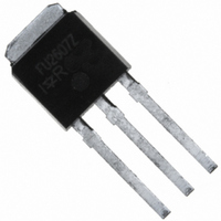
MOSFET N-CH 75V 42A I-PAK
Manufacturer
International Rectifier
Series
HEXFET®r
Specifications of IRFU2607ZPBF
Fet Type
MOSFET N-Channel, Metal Oxide
Fet Feature
Standard
Rds On (max) @ Id, Vgs
22 mOhm @ 30A, 10V
Drain To Source Voltage (vdss)
75V
Current - Continuous Drain (id) @ 25° C
42A
Vgs(th) (max) @ Id
4V @ 50µA
Gate Charge (qg) @ Vgs
51nC @ 10V
Input Capacitance (ciss) @ Vds
1440pF @ 25V
Power - Max
110W
Mounting Type
Through Hole
Package / Case
IPak, TO-251, DPak, VPak (3 straight leads + tab)
Transistor Polarity
N Channel
Continuous Drain Current Id
45A
Drain Source Voltage Vds
75V
On Resistance Rds(on)
17.6mohm
Rds(on) Test Voltage Vgs
10V
Threshold Voltage Vgs Typ
4V
Rohs Compliant
Yes
Operating Temperature Range
-55°C To +175°C
Drain-source Breakdown Voltage
75 V
Gate-source Breakdown Voltage
20 V
Continuous Drain Current
45 A
Power Dissipation
110 W
Mounting Style
SMD/SMT
Gate Charge Qg
34 nC
Lead Free Status / RoHS Status
Lead free / RoHS Compliant


‚
ƒ
www.irf.com
Notes:
IR WORLD HEADQUARTERS: 233 Kansas St., El Segundo, California 90245, USA Tel: (310) 252-7105
Repetitive rating; pulse width limited by
Pulse width
max. junction temperature. (See fig. 11).
R
recommended for use above this value.
Limited by T
G
= 25 , I
AS
Jmax
1.0ms; duty cycle
= 30A, V
, starting T
GS
=10V. Part not
J
= 25°C, L = 0.21mH
NOTES :
1. CONTROLLING DIMENSION : MILLIMETER.
2. ALL DIMENSIONS ARE SHOWN IN MILLIMETERS ( INCHES ).
3. OUTLINE CONFORMS TO EIA-481 & EIA-541.
12.1 ( .476 )
11.9 ( .469 )
NOTES :
1. OUTLINE CONFORMS TO EIA-481.
2%.
13 INCH
TR
Visit us at www.irf.com for sales contact information.09/2010
„
…
†
‡ When mounted on 1" square PCB (FR-4 or G-10 Material) .
ˆ
FEED DIRECTION
This product has been designed for the Industrial market.
C
as C
Data and specifications subject to change without notice.
Limited by T
This value determined from sample failure population. 100%
oss
application note #AN-994
tested to this value in production.
For recommended footprint and soldering techniques refer to
avalanche performance.
Qualification Standards can be found on IR’s Web site.
16.3 ( .641 )
15.7 ( .619 )
eff. is a fixed capacitance that gives the same charging time
oss
while V
Jmax
DS
8.1 ( .318 )
7.9 ( .312 )
is rising from 0 to 80% V
, see Fig.12a, 12b, 15, 16 for typical repetitive
TRR
16 mm
TRL
FEED DIRECTION
TAC Fax: (310) 252-7903
16.3 ( .641 )
15.7 ( .619 )
DSS
.
11
Related parts for IRFU2607ZPBF
Image
Part Number
Description
Manufacturer
Datasheet
Request
R

Part Number:
Description:
SCHOTTKY RECTIFIER
Manufacturer:
International Rectifier Corp.
Datasheet:
Part Number:
Description:
SCHOTTKY RECTIFIER
Manufacturer:
International Rectifier Corp.
Datasheet:
Part Number:
Description:
SCHOTTKY RECTIFIER
Manufacturer:
International Rectifier Corp.
Datasheet:
Part Number:
Description:
SCHOTTKY RECTIFIER
Manufacturer:
International Rectifier Corp.
Datasheet:
Part Number:
Description:
SCHOTTKY RECTIFIER
Manufacturer:
International Rectifier Corp.
Datasheet:
Part Number:
Description:
SCHOTTKY RECTIFIER
Manufacturer:
International Rectifier Corp.
Datasheet:
Part Number:
Description:
SCHOTTKY RECTIFIER
Manufacturer:
International Rectifier Corp.
Datasheet:
Part Number:
Description:
SCHOTTKY RECTIFIER
Manufacturer:
International Rectifier Corp.
Datasheet:
Part Number:
Description:
SCHOTTKY RECTIFIER
Manufacturer:
International Rectifier Corp.
Datasheet:
Part Number:
Description:
SCHOTTKY RECTIFIER
Manufacturer:
International Rectifier Corp.
Datasheet:
Part Number:
Description:
SCHOTTKY RECTIFIER
Manufacturer:
International Rectifier Corp.
Datasheet:
Part Number:
Description:
SCHOTTKY RECTIFIER
Manufacturer:
International Rectifier Corp.
Datasheet:
Part Number:
Description:
SCHOTTKY RECTIFIER
Manufacturer:
International Rectifier Corp.
Datasheet:
Part Number:
Description:
SCHOTTKY RECTIFIER
Manufacturer:
International Rectifier Corp.
Datasheet:
Part Number:
Description:
SCHOTTKY RECTIFIER
Manufacturer:
International Rectifier Corp.
Datasheet: