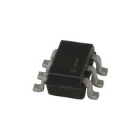
CAT5129TDI-10-T3 ON Semiconductor, CAT5129TDI-10-T3 Datasheet

CAT5129TDI-10-T3
Specifications of CAT5129TDI-10-T3
Related parts for CAT5129TDI-10-T3
CAT5129TDI-10-T3 Summary of contents
Page 1
Digitally Programmable Potentiometer (DPP™) FEATURES 32-position linear taper potentiometer Non-volatile EEPROM wiper storage Low standby current Single supply operation: 2.5V – 5.5V Increment Up/Down serial interface Resistance values: 10kΩ, 50kΩ and 100kΩ CAT5127 in tiny 8-lead 2mm x 2.5mm ...
Page 2
CAT5127, CAT5129 PIN CONFIGURATION MSOP/TDFN CAT5127 ¯¯¯ INC CC U/D ¯ ¯¯ GND TSOT23-6 CAT5129 ¯¯ GND ...
Page 3
DEVICE OPERATION The CAT5127 operates like a digitally controlled variable resistor with R and R equivalent to the high H L and low terminals. There are 32 available tap posi- tions including the resistor end points, R There are 31 ...
Page 4
CAT5127, CAT5129 ABSOLUTE MAXIMUM RATINGS Parameters Ratings Supply Voltage V to GND -0.5 to +7V CC Inputs ¯¯ to GND -0 +0 ¯¯¯ to GND INC -0 +0.5 CC U/D ¯ to GND -0.5 ...
Page 5
DC ELECTRICAL CHARACTERISTICS V = +2.5V to +5.5V unless otherwise specified CC Power Supply Symbol Parameter V Operating Voltage Range CC CAT5127 Supply Current (Increment) I CC1 CAT5129 Supply Current (Increment) I Supply Current (Write) CC2 (1) I Supply Current ...
Page 6
CAT5127, CAT5129 POTENTIOMETER CHARACTERISTICS Symbol Parameter R Potentiometer Resistance POT R Pot Resistance Tolerance TOL V Voltage on R pin Voltage on R pin RL L RES Resolution INL Integral Linearity Error DNL Differential Linearity Error R ...
Page 7
AC TEST CONDITIONS V Range 2.5V ≤ Input Pulse Levels 0.2V Input Rise and Fall Times 10ns Input Reference Levels 0.5V AC OPERATING CHARACTERISTICS V = +2.5V to +5.5V ...
Page 8
CAT5127, CAT5129 APPLICATION INFORMATION Potentiometer Configurations (a) resistive divider Applications (-) – 2 +5V DPP ...
Page 9
PACKAGE OUTLINE DRAWING MSOP 8-Lead 3.0 x 3.0mm ( TOP VIEW SIDE VIEW For current Tape and Reel information, download the PDF file from: http://www.catsemi.com/documents/tapeandreel.pdf. Notes: (1) All dimensions are in millimeters. Angles ...
Page 10
CAT5127, CAT5129 TDFN 8-Lead 2.5 x 2.0mm SYMBOL MIN NOM A 0.70 0.75 A1 0.00 0.02 A3 0.20 REF b 0.20 0.25 D 1.90 2.00 D2 1.40 1.50 E 2.40 2.50 E2 1.20 1.30 e 0.50 TYP L 0.20 0.30 ...
Page 11
TSOT-23 6-Lead (TD TOP VIEW SIDE VIEW For current Tape and Reel information, download the PDF file from: http://www.catsemi.com/documents/tapeandreel.pdf. Notes: (1) All dimensions are in millimeters. Angles in degrees. (2) Complies with JEDEC specification MO-193. © Catalyst Semiconductor, ...
Page 12
... CAT5127ZI-50-T3 CAT5127ZI-00-T3 CAT5127ZI-10-GT3 CAT5127ZI-50-GT3 CAT5127ZI-00-GT3 CAT5127ZD7I-10-GT3 CAT5127ZD7I-50-GT3 CAT5127ZD7I-00-GT3 CAT5129 CAT5129TDI-10-T3 CAT5129TDI-50-T3 CAT5129TDI-00-T3 CAT5129TDI-10-GT3 CAT5129TDI-50-GT3 CAT5129TDI-00-GT3 Notes: (1) All packages are RoHS-compliant (Lead-free, Halogen-free). (2) The standard lead finish is NiPdAu. (3) The device used in the above example is a CAT5127ZI-10-GT3 (MSOP, Industrial Temperature range, 10kΩ, NiPdAu, Tape & Reel). ...
Page 13
REVISION HISTORY Date Rev. Reason 12/18/06 A Initial Issue Updated the Functional Diagram 02/23/07 B Updated the DC Electrical Characteristics table Updated Package Outline Drawing 08/03/07 C Updated Ordering Information Copyrights, Trademarks and Patents © Catalyst Semiconductor, Inc. Trademarks and ...


