FLK-TI55FT-20 Fluke, FLK-TI55FT-20 Datasheet - Page 4
FLK-TI55FT-20
Manufacturer Part Number
FLK-TI55FT-20
Description
THERMAL IMAGER, -20°C TO 600°C
Manufacturer
Fluke
Datasheet
1.FLK-TI55FT-20.pdf
(6 pages)
Specifications of FLK-TI55FT-20
Temperature Measuring Range
-20° To 600°C (-4° To 1112°F)
Temperature Tester Type
Thermal Imager
Accuracy %
2%
Lead Free Status / RoHS Status
na


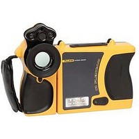
The Ti20 brings the powerful diagnostic capabilities of
infrared thermal imaging technology within reach of a
wider range of industrial applications. It is easy to operate
by the service and maintenance personnel who know and
understand the equipment best.
Point-and-shoot simplicity
Easy to use thanks to ‘point-and-
shoot’ operation and intuitive on-
screen guidance, the Ti20 user does
not require specialist training to
operate the images. Just point at the
target, focus the instrument and it
automatically adjusts the temperature
range for a detailed image. The image
and associated measurement data
(fully radiometric) is stored for later
analysis using the powerful InsideIR
software (supplied).
Radiometric measurement - the ‘data behind the picture’
Fully radiometric thermal imagers capture and store
calibrated temperature data for thousands of points in a
thermal image matrix. This makes it possible to perform
detailed analysis and change key parameters like emissivity
or temperature level and span either in the field on the
camera or later using the PC software.
The thermal imager for everyday
maintenance and inspection
Fluke Ti20 Thermal Imager
TM
Inspection routing - improving
maintenance performance
An inspection route details the
frequency, sequence and physical
route of equipment that needs to be
inspected. The InsideIR software
facilitates setting up such an
inspection route using unique location
names, measurement setup data and
high / low temperature alarms. These
routes can be uploaded to the imager
for use as a routing guide.
During an inspection, the on-camera
instructions help the user navigate to
the next image location on the route.
The new image can be compared to
the previous image, on the camera or
in the software, helping to identify
potential problems before they cause
failure.
180.1
181.2
182.0
181.1
181.3
181.4
178.4
178.6
179.1
179.3
178.5
179.2
99.1
98.4
98.9
98.7
99.1
98.8
90.2
91.1
91.0
91.1
91.1
90.4