N2791A AGILENT TECHNOLOGIES, N2791A Datasheet
N2791A
Specifications of N2791A


N2791A Summary of contents
Page 1
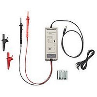
... Oscilloscope users often need to make floating measurements where neither point of the measurement is at earth ground. Use the N2790A, N2791A or N2891A high-voltage differential probe to make safe and accurate floating measurements with an oscilloscope. The N2790A, N2791A and N2891A high-voltage differential probes allow conventional earth-grounded Agilent oscilloscopes to be used for floating signal measurements ...
Page 2
... With a differential amplifier in the probe head, the N2790A is rated to measure differential voltage up to 1,400 VDC + peak AC with high CMRR (common mode rejection ratio) of > MHz. The N2791A and N2891A can measure differential voltage up to 700 V and 7 kV differential or common mode respectively. The N2790A, N2791A and ...
Page 3
Frequency (Hz) Figure 4. Vout/Vin vs. frequency response of N2790A Figure 5. Frequency response (Vout/Vin) of N2790A when inputs are driven in common (common mode rejection) Figure 6. Input impedance vs. ...
Page 4
... Figure 7. Voltage derating curve of N2790A (voltage between either input and ground) Figure 8. Vout/Vin vs. frequency response of N2791A Figure 9. Frequency response (Vout/Vin) of N2791A when inputs are driven in common (common mode rejection) ...
Page 5
... Figure 10. Input impedance vs. frequency of N2791A Figure 11. Voltage derating curve of N2791A (voltage between either input and ground) 5 ...
Page 6
Figure 12. Vout/Vin vs. Frequency response of N2891A at 1000:1 attenuation Figure 13. Frequency response (Vout/Vin) of N2891A when inputs are driven in common (common mode rejection) ...
Page 7
Figure 14. Input impedance vs. Frequency of N2891A Figure 15. Voltage derating curve of N2891A (voltage between either input and ground) 7 ...
Page 8
... ID tags - DC offset adjustment tool - manual Safety specifications IEC61010-031 * denotes warranted specification after 20 minute warm-up, all others are typical 8 (black and red) N2791A N2891A ≥ 25 MHz probe ≥70 MHz bandwidth ≤ ≤5 nsec 10:1 / 100:1 100:1 / 1000:1 ...
Page 9
... Probe tip accessory kit for N2790A including 2 each of browser tips, alligator plunger clips and pincer clips N2791A 25-MHz high-voltage differential probe N2791A-68700 Probe tip accessory kit for N2791A including 2 alligator clips and 2 hook clips N2891A 70-MHz high-voltage differential probe N2891A-68700 Probe tip accessory kit for N2891A including 2 high-voltage ...
Page 10
... Spain 34 (91) 631 3300 Sweden 0200- United Kingdom 44 (0) 118 9276201 For other unlisted Countries: www.agilent.com/find/contactus Revised: October 14, 2010 Product specifications and descriptions in this document subject to change without notice. © Agilent Technologies, Inc. 2010 Printed in USA, November 25, 2010 5990-3780EN ...