19641 Desco, 19641 Datasheet - Page 3
19641
Manufacturer Part Number
19641
Description
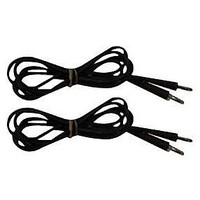
Test Leads, 1-Pair
Manufacturer
Desco
Type
Leads, Surface Resistance Checkerr
Datasheet
1.50003.pdf
(4 pages)
Specifications of 19641
Color
Black
Description/function
For use with 19640 surface resistance checker
Product
Static Monitors
For Use With
Desco 19640 Surface Resistance Checker
Lead Free Status / RoHS Status
na
Lead Free Status / RoHS Status
na
Available stocks
Company
Part Number
Manufacturer
Quantity
Price
Company:

Part Number:
196417-60041-3
Manufacturer:
I-PEX
Quantity:
1 093


TB-3037 Page 3 of 4
USING THE OPTIONAL TEST LEADS AND ONE OR
TWO 5 POUND ELECTRODES
GENERAL GUIDELINES
• Use both 5 pound electrodes for RTT
• Use one 5 pound electrode and one lead to groundable
• Ensure that the item being measured is electrically
• Ensure that the test leads are separated as a best
• When using the 5 pound electrodes:
• If surface has sections (floor tiles, garment panels), for
Recommended Frequency of Periodic Checks
of Installed Products
The ESD Association lists test procedures and
troubleshooting tips in Compliance Verification ESD TR53.
Note: “The frequency of periodic testing is normally
specified in corporate operating procedures. …The
frequency of testing is driven by the amount of risk
exposure that can occur between tests. For, example, what
is the quantity of product handled between test periods?”
(See ESD Handbook ESD TR20.20)
A GUIDE FOR PERIODIC TESTING
• Worksurface, Carts, Shelves - at least quarterly (see ESD
• Footwear - “Incoming inspection on a lot sampling basis
• Floor - “The types of monitoring and type of equipment
• Seating - “The recommended electrical resistance range
point for RTG (note: groundable points are usually snaps
installed on the material or workstation common point
ground)
isolated (i.e. placed on an insulative surface) as the
checker will measure the lowest resistance path
practice
• Place no closer than 2” from the edge of the surface
• Place no closer than 3” to any groundable point
• Place the 5 pound electrodes about 10” apart for RTT
• Preferred placements include: most commonly used
• For RTG, connect the banana plug to groundable point
RTT place the 5 pound electrodes on different sections
TR20.20 section 5.3.1.13 Periodic Tests)
should be performed for all static control footwear.” (see
ESD TR20.20 section 5.3.3.4 Testing)
are considerations. In some cases, a simple electrical
resistance test with a megohmmeter may suffice. In
others, a static charge generation test may be required.”
(see ESD TR20.20 section 5.3.4.13 Performance
Monitoring)
for seating is less than 1 x 10E9 ohms as tested in
accordance with ANSI/ESD STM 12.1. This value should
be during acceptance testing, installation and periodically
thereafter.” (see ESD TR20.20 section 5.3.5.3 Testing)
being measured
of worksurface and 3’ for floor
surface portion, most worn, center, and furthest from
groundable point.
DESCO EAST - One Colgate Way, Canton, MA 02021-1407 • (781) 821-8370 • Fax (781) 575-0172 • Website:
DESCO WEST - 3651 Walnut Avenue, Chino, CA 91710 • (909) 627-8178 • Fax (909) 627-7449
• Garments - “To maintain process control, it is imperative
Figure 4. Using the test leads and one 5 pound electrode to
measure RTG
Figure 5. Using the test leads and two 5 pound electrodes
to measure RTT
that the garment be tested per ANSI/ESD STM 2.1. The
point-to-point and sleeve-to-sleeve resistance test should
be made.” (see ESD TR20.20 section 5.3.13.3.1.8
Periodic Testing)
10”
Desco.com
© 2009 DESCO INDUSTRIES INC.
Employee Owned