U2001A AGILENT TECHNOLOGIES, U2001A Datasheet - Page 10
U2001A
Manufacturer Part Number
U2001A
Description
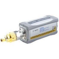
USB POWER SENSOR, 6GHZ, -60DBM To +20DBM
Manufacturer
AGILENT TECHNOLOGIES
Datasheet
1.U2001A.pdf
(23 pages)
Specifications of U2001A
Frequency Measuring Range
10MHz To 6GHz
Amplitude Accuracy
± 3%
Standing Wave Ratio
1.19
Connector Type
N
External Height
35.9mm
External Width
46mm
External Depth
163.75mm
Lead Free Status / RoHS Status
na


Specifications (continued)
Switching point
The U2000 Series power sensors have two measurement paths: a low power path and a high power path, as shown in the table below.
Each power sensor automatically
selects the proper power level path.
To avoid unnecessary switching when
the power level is close to the switch-
ing point, switching point hysteresis
has been added.
Offset at switching point:
≤ ± 0.5% (≤ ± 0.02 dB) typical
Switching point hysteresis:
± 0.5 dBm typical
Power accuracy
Average only Mode Power Accuracy
Specifications valid with the following conditions:
• After zeroing
• Number of averages = 1024
• After 30 minutes of power-on warm-up
Normal Mode Power Accuracy
1. This accuracy is essentially a combination of linearity, instrumentation accuracy, and traceability to absolute accuracy at 50 MHz, 0 dBm.
2. The accuracy for –7 to +1 dBm (U2000/1/2A), +3 to +11 dBm (U2000/1/2H), and +23 to +31 dBm (U2000/1B) power level will be dominated by
3. It is advisable to perform external zeroing on the U2000 Series power sensor for power measurement level below –30 dBm. During the external
Models
U2000/1/2/4A
U2000/1/2H
U2000/1B
Model
U2000/1/2/4A
U2000/1/2H
U2000/1B
Model
U2000/1/2/A
U2000/1/2H
U2000/1B
Note: Mismatch uncertainty, calibration factor uncertainty, and power level dependent terms (zero set, drift, and noise) are excluded in this
specification and specified elsewhere in the data sheet.
zero set and measurement noise. For overall accuracy, refer to the measurement uncertainty calculator which is available on the Agilent Technologies
Web site.
zeroing process, the RF input signal must be switched off or the device-under-test disconnected from the U2000 Series power sensor.
3
AUTO (default) range
–60 to +20 dBm
–50 to +30 dBm
–30 to +44 dBm
Power range
–60 to +20 dBm
–50 to +30 dBm
–30 to +44 dBm
Power level
–30 to +20 dBm
–20 to +30 dBm
0 to +44 dBm
1, 2
(with exclusions)
1
(with exclusions)
Example with U2000 “A” suffix
sensors: Switching point for the
U2000/1/2/4A sensors is at –7 dBm.
Hysteresis causes the low power
path to remain selected until approxi-
mately –6.5 dBm as the power level
is increased. Above this power, the
high power path is selected. The high
power path remains selected until
approximately –7.5 dBm is reached
as the signal level decreases. Below
this power, the low power path is
selected.
Accuracy
±3.0%
±4.0%
±3.5%
Accuracy (25 °C ± 10 °C)
±4.0%
±5.0%
±4.5%
Low power path
–60 to –7 dBm
–50 to +3 dBm
–30 to +23 dBm
1
10
(25 °C ± 10 °C)
High power path
–7 to +20 dBm
+3 to +30 dBm
+23 to +44 dBm
Accuracy
±3.5%
±5.0%
±4.0%
1
(0 °C to 55 °C)
Switching point
–7 dBm
+3 dBm
+23 dBm