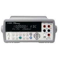
34411A AGILENT TECHNOLOGIES, 34411A Datasheet - Page 9

34411A
Manufacturer Part Number
34411A
Description
MULTIMETER, DIGITAL, BENCH, 6-1/2 DIGIT
Manufacturer
AGILENT TECHNOLOGIES
Datasheet
1.34410A.pdf
(20 pages)
Specifications of 34411A
Dmm Type
Bench
Voltage Measuring Range Dc
100mV To 1000V
Voltage Measuring Range Ac
100mV To 750V
Current Measuring Range Dc
100µA To 3A
Current Measuring Range Ac
100µA To 3A
Lead Free Status / RoHS Status
na
Level triggering with scope-
like waveform capture
Aerospace and automotive
applications are replete with
mechanical-electrical signals.
There are mechanical parts
that oscillate, vibrate, and
experience tension or compres-
sion. The frequency content
of these signals is relatively
low, often less than 8 kHz. For
example, a typical accelerometer
will have a bandwidth of 2.5 kHz.
The 34411A provides waveform
capture for these types of signals
using the following capabilities:
• 50-kHz sample rate at
• Bandwidth response relatively
• Analog level trigger
• Pre- and post-trigger sampling
• 1-million-reading storage
• 270-k readings/s access
Figure 4. Using level triggering to digitize current drawn from a digital camera battery
4.5 digits using a low-jitter
sample timer
flat (< 0.1 dB at 3 kHz;
< 0.6 dB at 8 kHz)
to reading storage
Pre-Trigger
Count
Level Trigger
Post-Trigger
Count
Electronic signals generated in
functional test applications
also are often below 8 kHz:
voice signals of 300 Hz to 3 kHz,
battery drain in handheld
devices such as cell phones,
cameras, or PDAs, and other
low-frequency-content signals.
The measurement of current
drain in handheld devices is
commonplace in the electronics
industry. Long battery life is
a key factor in customer satis-
faction. It is important to
understand the current drain
for various operations of a
handheld device.
Some Agilent power supplies
can sample accurately at
microampere levels the current
waveform supplied to a device
under test. The Agilent N6700
power supplies provide this
capability. However, the mea-
surement is limited to the cur-
rent coming out of the supply.
9
3 seconds
Once a test system determines
that too much current is being
drawn from the battery, a
number of other test points
are typically tested to see which
sections of the hand-held device
are on when they should or
should not be on, and for
how long. This test requires
waveform capture to check
the timing of current usage.
The waveform in Figure 4 is
the current drain from a cam-
era that has just been actuated
to take a picture. In this case,
this is the voltage across a cur-
rent shunt. Represented in the
waveform are the mechanical
movements of the auto focus,
processing the picture, driving
the display and status LED’s,
and storing the result in
flash memory.


