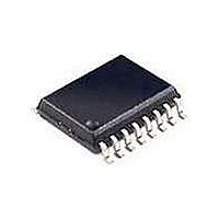
Si3016-KS Silicon Laboratories Inc, Si3016-KS Datasheet - Page 22

Si3016-KS
Manufacturer Part Number
Si3016-KS
Description
Telecom Line Management ICs Line-Side device for processors
Manufacturer
Silicon Laboratories Inc
Type
Chipsetr
Datasheet
1.SI3016-F-FS.pdf
(50 pages)
Specifications of Si3016-KS
Product
Modem Module
Interface Type
Wire
Supply Current
0.3 mA
Maximum Operating Temperature
+ 70 C
Minimum Operating Temperature
0 C
Mounting Style
SMD/SMT
Package / Case
SOIC-16
Lead Free Status / RoHS Status
Lead free / RoHS Compliant
Available stocks
Company
Part Number
Manufacturer
Quantity
Price
Part Number:
SI3016-KS
Manufacturer:
SI
Quantity:
20 000
Part Number:
Si3016-KSR
Manufacturer:
SILICON LABS/芯科
Quantity:
20 000
Si3016
4. If a non-compliant parallel device is present, a reply
5. If all devices on the line are Type II CID compliant,
6. The CO then responds with the CID data. After
Notes:
4.19. Overload Protection
The Si3016 can detect if an overload condition capable
of damaging the DAA circuit is present. The DAA may
be damaged if excessive line voltage or loop current is
sustained.
The overload protection circuit utilizes the LVCS bits to
determine an excessive line current or voltage per the
LVCS bit transfer functions outlined in Figures 8 and 9.
When off-hook, if OPE is set and LVCS = 11111, the dc
termination is disabled (800 Ω presented to the line), the
hookswitch current is reduced, and the OPD bit is set.
22
O NHM Bit
M O DE Bit
CALD Bit
tone is not sent by the host tone generator, and the
CO does not proceed with sending the CID data.
the host must mute its upstream data output to avoid
the propagation of its reply tone and the subsequent
CID data. After muting its upstream data output, the
host processor must then send an
acknowledgement (ACK) tone back to the CO to
request the transmission of the CID data.
receiving this, the host processor unmutes the
upstream data output and continues with normal
1. The off-hook counter is used to prevent transmission or reception of data for 1548/Fs to allow time for the line voltage to
2. The caller alert signal (CAS) tone is transmitted from the CO, which signals an incoming call.
3. When the MODE bit is set while the device is off-hook, the device is forced on-hook. This is done to read the line voltage
4. When the device returns off-hook after being forced on-hook using the MODE bit, the normal off-hook counter is
5. After allowing the line voltage to settle in fast DCT mode, normal off-hook mode should be entered by disabling the
O H Bit
LINE
settle. If the CALD bit is 0, an automatic calibration will also be performed during this time.
in the LVCS bits to detect parallel handsets. In this mode, no data is transmitted on the SDO pin.
disabled. Additionally, if the CALD bit is set, the automatic calibration will not be performed. The fast DCT mode must be
manually enabled for at least 30 ms in order to properly settle the line voltage. This is done by setting the ONHM bit after
disabling the MODE bit.
ONHM bit. If CID data reception is desired, the appropriate signal should be sent to the CO at this time.
On-Hook
Figure 15. Implementing Type II Caller ID on the Si3016
Off-Hook Counter
(1548/Fs)
1
Off-Hook
Rev. 1.0
7. The muting of the upstream data path by the host
8. The CALD bit can be set to 0 to reenable the
Due to the nature of the low-power ADC, the data
presented on SDO could have up to a 10% dc offset.
The caller ID decoder must use either a high-pass or a
band-pass filter to accurately retrieve the caller ID data.
Note: If the OPE bit is enabled before going off-hook, the
4.20. Analog Output
The integrated system-side module that the Si3016 is
connected to supports an analog output (AOUT) for
driving the call progress speaker found with most of
today’s modems. AOUT is an analog signal that is
comprised of a mix of the transmit and receive signals.
CAS Tone
Received
operation.
processor has the effect of muting the handset in a
telephone application so the user cannot hear the
acknowledgement tone and CID data being sent.
automatic calibration when going off-hook.
overload protection circuit can be activated by the line
transients produced by going off-hook. To avoid this,
the OPE bit should be 0 prior to going off-hook. This bit
can then be set ~25 ms after going off-hook to enable
the overload protection feature.
2
Force On-Hook
3
Fast DCT Mode
30 m s
4
Off-Hook
Ack
5


