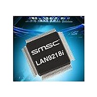
LAN9218I-MT SMSC, LAN9218I-MT Datasheet - Page 77

LAN9218I-MT
Manufacturer Part Number
LAN9218I-MT
Description
Ethernet ICs Indust Hi Perfrm Single-Chip
Manufacturer
SMSC
Type
Single Chip MAC and PHY Controllerr
Datasheet
1.LAN9218I-MT.pdf
(133 pages)
Specifications of LAN9218I-MT
Ethernet Connection Type
10 Base-T, 100 Base-TX
Minimum Operating Temperature
- 40 C
Mounting Style
SMD/SMT
Product
Ethernet Controllers
Number Of Transceivers
1
Standard Supported
802.3, 802.3u
Data Rate
10 Mbps, 100 Mbps
Supply Voltage (max)
3.3 V
Supply Voltage (min)
0 V
Supply Current (max)
69 mA
Maximum Operating Temperature
+ 85 C
Package / Case
TQFP-100
Lead Free Status / RoHS Status
Lead free / RoHS Compliant
Available stocks
Company
Part Number
Manufacturer
Quantity
Price
Company:
Part Number:
LAN9218I-MT
Manufacturer:
Standard
Quantity:
1 981
Company:
Part Number:
LAN9218I-MT
Manufacturer:
SMSC
Quantity:
6
Part Number:
LAN9218I-MT
Manufacturer:
SMSC
Quantity:
20 000
High-Performance Single-Chip 10/100 Ethernet Controller with HP Auto-MDIX and Industrial Temperature Support
Datasheet
SMSC LAN9218i
5.3.9
31-25
23-21
16-19
BITS
15-3
24
20
2
1
0
Reserved
AMDIX_EN Strap State. This read-only bit reflects the state of the
AMDIX_EN strap pin (pin 73). This pin can be overridden by PHY Registers
27.15 and 27.13
Reserved
Must Be One (MBO). This bit must be set to “1” for normal device
operation.
TX FIFO Size (TX_FIF_SZ). Sets the size of the TX FIFOs in 1KB values
to a maximum of 14KB. The TX Status FIFO consumes 512 bytes of the
space allocated by TX_FIF_SIZ, and the TX data FIFO consumes the
remaining space specified by TX_FIF_SZ. The minimum size of the TX
FIFOs is 2KB (TX data and status combined). The TX data FIFO is used for
both TX data and TX commands.
The RX status and data FIFOs consume the remaining space, which is
equal to 16KB – TX_FIF_SIZ. See
Configurable FIFO Memory Allocation," on page 78
Reserved
32/16-bit Mode. When set, the LAN9218i is set for 32-bit operation. When
clear, it is configured for 16-bit operation. This field is the value of the
D32/nD16 strap.
Soft Reset Time-out (SRST_TO). If a software reset is attempted when the
internal PHY is not in the operational state (RX_CLK and TX_CLK running),
the reset will not complete and the soft reset operation will time-out and this
bit will be set to a ‘1’. The host processor must correct the problem and
issue another soft reset.
Soft Reset (SRST). Writing 1 generates a software initiated reset. This reset
generates a full reset of the MAC CSR’s. The SCSR’s (system command
and status registers) are reset except for any NASR bits. Soft reset also
clears any TX or RX errors (TXE/RXE). This bit is self-clearing.
Notes:
Do not attempt a soft reset unless the internal PHY is fully awake and
operational. After a PHY reset, or when returning from a reduced power
state, the PHY must be given adequate time to return to the operational
state before a soft reset can be issued. The internal RX_CLK and TX_CLK
signals must be running for a proper software reset. Please refer to
Section 6.8, "Reset Timing," on page 122
The LAN9218i must always be read at least once after power-up, reset,
or upon return from a power-saving state or write operations will not
function.
HW_CFG—Hardware Configuration Register
Note: The transmitter and receiver must be stopped before writing to this register. Refer to
Offset:
3.11.8, "Stopping and Starting the Transmitter," on page 51
Starting the Receiver," on page 55
DESCRIPTION
74h
Section 5.3.9.1, "Allowable settings for
DATASHEET
for details on PHY reset timing.
77
for details on stopping the transmitter and receiver.
for more information.
Size:
and
32 bits
Section 3.12.4, "Stopping and
TYPE
R/W
R/W
RO
RO
RO
RO
RO
RO
SC
Revision 2.7 (03-15-10)
DEFAULT
AMDIX
Strap
Pin
5h
0
0
0
-
-
-
-
Section


