ZVN4525ZTA Diodes Zetex, ZVN4525ZTA Datasheet - Page 2
ZVN4525ZTA
Manufacturer Part Number
ZVN4525ZTA
Description
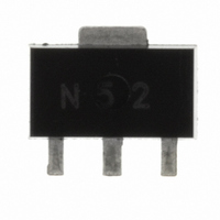
MOSFET N-CH 250V 240MA SOT-89
Manufacturer
Diodes Zetex
Datasheet
1.ZVN4525ZTA.pdf
(8 pages)
Specifications of ZVN4525ZTA
Fet Type
MOSFET N-Channel, Metal Oxide
Fet Feature
Logic Level Gate
Rds On (max) @ Id, Vgs
8.5 Ohm @ 500mA, 10V
Drain To Source Voltage (vdss)
250V
Current - Continuous Drain (id) @ 25° C
240mA
Vgs(th) (max) @ Id
1.8V @ 1mA
Gate Charge (qg) @ Vgs
3.65nC @ 10V
Input Capacitance (ciss) @ Vds
72pF @ 25V
Power - Max
1.2W
Mounting Type
Surface Mount
Package / Case
SC-62, SOT-89, TO-243 (3 Leads + Tab)
Lead Free Status / RoHS Status
Lead free / RoHS Compliant
Other names
ZVN4525ZTR


ABSOLUTE MAXIMUM RATINGS.
THERMAL RESISTANCE
NOTES
(a) For a device surface mounted on 25mm x 25mm FR4 PCB with high coverage of single sided 1oz copper,
in still air conditions
(b) For a device surface mounted on FR4 PCB measured at t 5 secs.
(c) Repetitive rating - pulse width limited by maximum junction temperature. Refer to Transient Thermal
NB High Voltage Applications
For high voltage applications, the appropriate industry sector guidelines should be considered with regard to
voltage spacing between conductors.
ZVN4525Z
PARAMETER
Drain-Source Voltage
Gate Source Voltage
Continuous Drain Current (V
Pulsed Drain Current (c)
Continuous Source Current (Body Diode)
Pulsed Source Current (Body Diode)
Power Dissipation at T
Linear Derating Factor
Operating and Storage Temperature Range
PARAMETER
Junction to Ambient (a)
Junction to Ambient (b)
A
=25°C (a)
(V
GS
GS
=10V; TA=25°C)(a)
=10V; TA=70°C)(a)
SYMBOL
R
R
2
SYMBOL
V
V
I
I
I
I
I
P
T
D
D
DM
S
SM
JA
JA
D
j
DSS
GS
:
T
stg
-55 to +150
VALUE
LIMIT
103
50
1.44
1.44
250
240
192
1.1
1.2
9.6
40
ISSUE 1 - MARCH 2001
mW/°C
UNIT
°C/W
°C/W
UNIT
mA
mA
W
°C
A
A
A
V
V
Related parts for ZVN4525ZTA
Image
Part Number
Description
Manufacturer
Datasheet
Request
R

Part Number:
Description:
DIODE ZENER 13V 500MW SOD-123
Manufacturer:
Diodes Zetex
Datasheet:

Part Number:
Description:
DIODE ZENER 13V 200MW SOD-323
Manufacturer:
Diodes Zetex
Datasheet:

Part Number:
Description:
DIODE ZENER 27V 500MW MINIMELF
Manufacturer:
Diodes Zetex
Datasheet:
Part Number:
Description:
DIODE ZENER 16V 200MW SOD-323
Manufacturer:
Diodes Zetex
Datasheet:
Part Number:
Description:
DIODE ZENER 28V 500MW SOD-123
Manufacturer:
Diodes Zetex
Datasheet:

Part Number:
Description:
DIODE ZENER 6.2V 200MW SC70-3
Manufacturer:
Diodes Zetex
Datasheet:

Part Number:
Description:
DIODE ZENER 3.6V 350MW SOT23-3
Manufacturer:
Diodes Zetex
Datasheet:

Part Number:
Description:
DIODE ZENER 4.3V 350MW SOT23-3
Manufacturer:
Diodes Zetex
Datasheet:
Part Number:
Description:
DIODE ZENER 13V 350MW SOT23-3
Manufacturer:
Diodes Zetex
Datasheet:
Part Number:
Description:
DIODE ZENER 16V 350MW SOT23-3
Manufacturer:
Diodes Zetex
Datasheet:

Part Number:
Description:
DIODE SW ARRAY 80V 200MW SOT363
Manufacturer:
Diodes Zetex
Datasheet:

Part Number:
Description:
DIODE SCHOTTKY 45V16A TO220-3
Manufacturer:
Diodes Zetex
Datasheet:
Part Number:
Description:
DIODE SCHOTTKY 45V 20A TO220-3
Manufacturer:
Diodes Zetex
Datasheet:
Part Number:
Description:
DIODE SW FAST DUAL CC SOT23-3
Manufacturer:
Diodes Zetex
Datasheet:
Part Number:
Description:
DIODE HI SPEED SW CC 70V SOT23-3
Manufacturer:
Diodes Zetex
Datasheet: