2N7002W-7-F Diodes Inc, 2N7002W-7-F Datasheet

MOSFET N-CH 60V 115MA SOT323

2N7002W-7-F

Manufacturer Part Number
2N7002W-7-F
Description
MOSFET N-CH 60V 115MA SOT323
Manufacturer
Diodes Inc
Datasheet

Specifications of 2N7002W-7-F

Fet Type
MOSFET N-Channel, Metal Oxide
Fet Feature
Standard
Rds On (max) @ Id, Vgs
7.5 Ohm @ 50mA, 5V
Drain To Source Voltage (vdss)
60V
Current - Continuous Drain (id) @ 25° C
115mA
Vgs(th) (max) @ Id
2V @ 250µA
Input Capacitance (ciss) @ Vds
50pF @ 25V
Power - Max
200mW
Mounting Type
Surface Mount
Package / Case
SC-70-3, SOT-323-3
Configuration
Single
Transistor Polarity
N-Channel
Resistance Drain-source Rds (on)
7.5 Ohm @ 5 V
Forward Transconductance Gfs (max / Min)
0.08 S
Drain-source Breakdown Voltage
60 V
Gate-source Breakdown Voltage
+/- 20 V
Continuous Drain Current
0.115 A
Power Dissipation
200 mW
Maximum Operating Temperature
+ 150 C
Mounting Style
SMD/SMT
Minimum Operating Temperature
- 55 C
Continuous Drain Current Id
800mA
Drain Source Voltage Vds
60V
On Resistance Rds(on)
13.5ohm
Rds(on) Test Voltage Vgs
10V
Threshold Voltage Vgs Typ
2V
Rohs Compliant
Yes
Lead Free Status / RoHS Status
Lead free / RoHS Compliant
Gate Charge (qg) @ Vgs
-
Lead Free Status / Rohs Status
Lead free / RoHS Compliant
Other names
2N7002W-FDITR

Available stocks

Company
Part Number
Manufacturer
Quantity
Price
Part Number:
2N7002W-7-F
Manufacturer:
DIO
Quantity:
156 000
Part Number:
2N7002W-7-F
Manufacturer:
DIODES
Quantity:
310
Part Number:
2N7002W-7-F
Manufacturer:
DIODES/美台
Quantity:
20 000
Company:
Part Number:
2N7002W-7-F
Quantity:
200 000
Thermal Characteristics
Maximum Ratings
Drain-Source Voltage
Drain-Gate Voltage R
Gain-Source Voltage
Drain Current (Note 1)
Total Power Dissipation (Note 1)
Derating above T
Thermal Resistance, Junction to Ambient
Operating and Storage Temperature Range
Features
Notes:
2N7002W
Document number: DS30099 Rev. 14 - 2
Low-On Resistance
Low Gate Threshold Voltage
Low Input Capacitance
Fast Switching Speed
Low Input/Output Leakage
Ultra-Small Surface Mount Package
Lead Free/RoHS Compliant (Note 2)
1. Device mounted on FR-4 PCB 1.0 x 0.75 x 0.062 inch pad layout as shown on Diodes, Inc. suggested pad layout AP02001, which can be found on our
2. No purposefully added lead.
website at http://www.diodes.com/datasheets/ap02001.pdf.
A
= 25°C
GS
≤ 1.0MΩ
Characteristic
Characteristic
@T
A
= 25°C unless otherwise specified
@T
A
Continuous @ 100°C
= 25°C unless otherwise specified
TOP VIEW
Continuous
Continuous
N-CHANNEL ENHANCEMENT MODE FIELD EFFECT TRANSISTOR
Pulsed
Pulsed
www.diodes.com
SOT-323
1 of 3
Mechanical Data
Symbol
Symbol
T
J
V
V
V
R
Please click here to visit our online spice models database.
, T
P
DGR
DSS
GSS
I
θ JA
D
Case: SOT-323
Case Material: Molded Plastic, "Green" Molding Compound,
Note 4. UL Flammability Classification Rating 94V-0
Moisture Sensitivity: Level 1 per J-STD-020D
Terminals: Finish - Matte Tin annealed over Alloy 42
leadframe. Solderable per MIL-STD-202, Method 208
Terminal Connections: See Diagram
Marking Information: See Page 3
Ordering Information: See Page 3
Weight: 0.006 grams (approximate)
D
STG
Gate
Equivalent Circuit
Drain
Source
-55 to +150
Value
Value
1.60
±20
±40
115
800
200
625
60
60
73
G
TOP VIEW
D
S
2N7002W
© Diodes Incorporated
°C /W
Unit
Unit
mW
mW
mA
°C
V
V
V
August 2008

Related parts for 2N7002W-7-F

2N7002W-7-F Summary of contents

Page 1

... TOP VIEW Equivalent Circuit Symbol V DSS V DGR Continuous V GSS Pulsed Continuous Continuous @ 100° Pulsed = 25°C unless otherwise specified A Symbol θ STG www.diodes.com 2N7002W Drain Source TOP VIEW Value Unit ±20 V ±40 115 73 mA 800 Value Unit 200 mW 1.60 mW °C /W 625 °C ...

Page 2

... I D(ON) ⎯ ⎯ iss ⎯ oss ⎯ C 2.0 rss ⎯ t 7.0 D(ON) ⎯ D(OFF 120 145 170 ° www.diodes.com 2N7002W Max Unit Test Condition ⎯ 0V 10μ 1.0 μ 60V 500 ±10 = ±20V 2 250μ 7 5.0V 0.05A Ω 13 10V 0. ⎯ A ...

Page 3

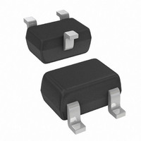
... Ordering Information (Notes 4) Part Number 2N7002W-7-F Notes: 4. For packaging details our website at http://www.diodes.com/datasheets/ap02007.pdf. Marking Information Date Code Key Year 1998 1999 2000 Code Month Jan Feb Mar Code 1 2 Package Outline Dimensions A TOP VIEW Suggested Pad Layout Diodes Incorporated and its subsidiaries reserve the right to make modifications, enhancements, improvements, corrections or other changes without further notice to any product herein. Diodes Incorporated does not assume any liability arising out of the application or use of any product described herein ...

Related keywords