585SX4Q25F103SP Honeywell, 585SX4Q25F103SP Datasheet - Page 8
585SX4Q25F103SP
Manufacturer Part Number
585SX4Q25F103SP
Description
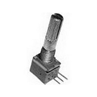
Potentiometers 10K Ohm 20% 1/20W 6mm
Manufacturer
Honeywell
Type
Potentiometerr
Series
585r
Specifications of 585SX4Q25F103SP
Resistance
10kohm
Power Rating
1/20W
Tolerance (+ Or -)
20%
Number Of Turns
1Turn
Technology
Carbon Film
Mounting Style
Panel
Termination Style
Pin
Operating Temp Range
-55C to 120C
Failure Rate
Not Required
Shaft Diameter (mm)
6mm
Product Diameter (mm)
Not Requiredmm
Product Length (mm)
19.5mm
Product Height (mm)
11.35mm
Product Depth (mm)
9.5mm
Tolerance
20 %
Taper
Linear
Element Type
Carbon
Shaft Type
Flatted / D
Shaft Length
19.05 mm
Shaft Diameter
6 mm
Product
Commercial Potentiometer
Voltage Rating
50 Volts
Angle, Mechanical
300 °
Application
For manual controls, telecommunications and audio equipment
Diameter, Shaft
0.236 "
Dimensions
9.5mmL×9.5mmW×5mmH
Linearity
±5 %
Material, Element
Carbon
Mounting Type
PCB
Power, Rating
0.05 W
Rotational Life
10000 Cycles
Shaft Style
Flatted Shaft
Termination
PC Pins
Voltage, Operating
50 VAC
Lead Free Status / RoHS Status
Compliant
Available stocks
Company
Part Number
Manufacturer
Quantity
Price

Part Number:
585SX4Q25F103SP
Manufacturer:
HONEYWELL
Quantity:
20 000


LIMIT SWITCHES
Proper application of limit switches
The following are guidelines for the correct application of Limit Switches.
Never use the Limit Switch as a physical end stop. Mechanical damage or
incorrect operation may occur if this is done. Always ensure that the
mechanical actuator is protected from excessive mechanical shock. Never
release the actuator suddenly - gradual actuation and release will ensure that
stress on the mechanics of the switch is kept to a minimum. This has the
added benefit that the switch life will be improved. The diagrams illustrate how
to actuate your limit switch for optimum performance.
Standards and Electrical rating
IEC/EN 60947-1 explains the general rules relating to Low Voltage switchgear
and controlgear. The purpose of this standard is to harmonize as much as
possible the product performance and test requirements for equipment where
the rated voltage does not exceed 1,000 Vac or 1,500 Vdc.
IEC 60947-5-1 is part 5 of the general rules which relates to Control-circuit
devices and switching elements, where rated voltage does not exceed 1,000
Vac or 600 Vdc. There are special requirements for control switches with
positive opening operation. These switches are marked on the outside with
this symbol:
The Contact Element form defines the configuration and number of contacts
within the switch.
Form Za – both contact elements have the same polarity
Form Zb – the two contact elements are electrically separated.
The Utilization Category defines the type of current carried – ac or dc – and
the typical application where the switch is used.
The contact rating Designation relates to the Utilization Categories and defines
the conventional thermal current Ith (a) rated operational current Ie (A) at
rated operational voltages Ue and the VA rating.
Actuators
A range of actuators is available for limit switches. Illustrations of actuator
types available from this catalogue are shown at the beginning of each
product family. Other actuators may be available - for more information
please contact your local Honeywell office.
Roller lever
pin plunger
6
Top roller
plunger
Side
roller plunger
Top roller
Top roller
boot seal
plunger,
lever
Side
perpendicular
Adjustable
roller lever
Roller lever
Top roller
plunger,
perpendicular,
Yoke lever
Top roller
boot seal
plunger,
plunger
Top pin
Ball bearing
Rod lever
boot seal
plunger,
Top pin
plunger
www.honeywell.com/sensing
Wobble head
WRONG
RIGHT
Cam or dog arrangements should be such that the actuator is not suddently released
to snap back freely.
Operating mechanisms for limit switches shoud be so designed that, under any
operating or emergency conditions, the limit switch is not operated beyond its
overtravel limit position. A limit switch should not be used as a mechanical stop.
For limit switches with lever actuators, the actuating force should be applied as
nearly perpendicular to the lever as practical and perpendicular to the shaft axis
about which the lever rotates.
For limit switches with pushrod actuators, the actuating force should be applied as
nearly as possible in line with the pushrod axis.
WRONG
RIGHT
non-over-riding
over-riding
WRONG
RIGHT
WRONG
RIGHT
over-riding
over-riding
cam
cam
WRONG
FIXED STOP
RIGHT
WRONG
RIGHT
free position
free position
WRONG
RIGHT
interference
end of
overtravel
operated
position
end of
overtravel
Related parts for 585SX4Q25F103SP
Image
Part Number
Description
Manufacturer
Datasheet
Request
R

Part Number:
Description:
HONEYWELL ZEPHYR DIGITAL AIRFLOW SENSORS: HAF SERIES-HIGH ACCURACY
Manufacturer:
HONEYWELL [Honeywell Solid State Electronics Center]
Datasheet:

Part Number:
Description:
MOUNTING BARRIER FOR HONEYWELL SERIES 2 OPERATOR INTERFACE PUSHBUTTON SWITCHES
Manufacturer:
Honeywell Sensing and Control
Part Number:
Description:
SEALED OI-SE SWITCH . PER TERRY @ HONEYWELL THERE IS A CHG OF $5.00 EACH FOR P
Manufacturer:
Honeywell Sensing and Control
Part Number:
Description:
LIMIT SWITCH-OT/HONEYWELL KOREA RELAYS (YKC)
Manufacturer:
Honeywell Sensing and Control
Part Number:
Description:
Honeywell Zephyr Digital Airflow Sensors Series-high Accuracy
Manufacturer:
Honeywell International's Solid State Electronics Center (SSEC)
Datasheet:

Part Number:
Description:
DIODE IR EMITTING GAAS SIDE LOOK
Manufacturer:
Honeywell Sensing and Control
Datasheet:

Part Number:
Description:
DIODE IR EMITTING ALGAAS TO-46
Manufacturer:
Honeywell Sensing and Control
Datasheet:

Part Number:
Description:
SENSOR AMP 150PSIS .5-4.5VDC OUT
Manufacturer:
Honeywell Sensing and Control
Datasheet:

Part Number:
Description:
SW MINI TOGGLE ON-OFF-ON SPDT
Manufacturer:
Honeywell Sensing and Control
Datasheet:

Part Number:
Description:
Board Mount Hall Effect / Magnetic Sensors 10mA 3.3V/5V 3-Pin
Manufacturer:
Honeywell
Part Number:
Description:
Board Mount Hall Effect / Magnetic Sensors Digital Position radial lead IC pkg
Manufacturer:
Honeywell
Datasheet:
Part Number:
Description:
Board Mount Hall Effect / Magnetic Sensors 20mA Unipolar 5V/9V/ 12V/15V/18V/24V 3Pin
Manufacturer:
Honeywell
Datasheet: