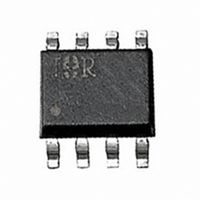
IRF7902PBF International Rectifier, IRF7902PBF Datasheet - Page 6

IRF7902PBF
Manufacturer Part Number
IRF7902PBF
Description
MOSFET N-CHAN DUAL 30V 8-SOIC
Manufacturer
International Rectifier
Series
HEXFET®r
Datasheet
1.IRF7902PBF.pdf
(10 pages)
Specifications of IRF7902PBF
Fet Type
2 N-Channel (Dual)
Fet Feature
Logic Level Gate
Rds On (max) @ Id, Vgs
22.6 mOhm @ 6.4A, 10V
Drain To Source Voltage (vdss)
30V
Current - Continuous Drain (id) @ 25° C
6.4A, 9.7A
Vgs(th) (max) @ Id
2.25V @ 25µA
Gate Charge (qg) @ Vgs
6.9nC @ 4.5V
Input Capacitance (ciss) @ Vds
580pF @ 15V
Power - Max
1.4W, 2W
Mounting Type
Surface Mount
Package / Case
8-SOIC (3.9mm Width)
Configuration
Dual
Transistor Polarity
Dual N-Channel
Resistance Drain-source Rds (on)
18.7 mOhms
Drain-source Breakdown Voltage
30 V
Gate-source Breakdown Voltage
20 V
Continuous Drain Current
6.4 A
Power Dissipation
2.0 W
Mounting Style
SMD/SMT
Gate Charge Qg
4.6 nC
Lead Free Status / RoHS Status
Lead free / RoHS Compliant
Available stocks
Company
Part Number
Manufacturer
Quantity
Price
Company:
Part Number:
IRF7902PBF
Manufacturer:
HRS
Quantity:
2 950
Fig 19. Maximum Drain Current vs. Ambient Temperature
Fig 23. Maximum Avalanche Energy vs. Drain Current
6
Fig 21. Threshold Voltage vs. Temperature
2.5
2.0
1.5
1.0
14
12
10
7
6
5
4
3
2
1
0
8
6
4
2
0
-75 -50 -25
25
25
Starting T J , Junction Temperature (°C)
T A , Ambient Temperature (°C)
50
50
T J , Temperature ( °C )
Q1 - Control FET
I D = 250µA
0
75
75
25
50
100
100
TOP
BOTTOM 6.4A
75 100 125 150
125
125
I D
2.4A
2.0A
Typical Characteristics
150
150
Fig 24. Maximum Avalanche Energy vs. Drain Current
Fig 20. Maximum Drain Current vs. Ambient Temperature
Fig 22. Threshold Voltage vs. Temperature
2.5
2.0
1.5
1.0
30
25
20
15
10
10
5
0
8
6
4
2
0
-75 -50 -25
25
25
Starting T J , Junction Temperature (°C)
T A , Ambient Temperature (°C)
50
50
T J , Temperature ( °C )
Q2 - Synchronous FET
I D = 250µA
0
75
75
25
50
100
100
TOP
BOTTOM 7.8A
75 100 125 150
125
125
www.irf.com
I D
2.4A
2.8A
150
150


