IRG4PSH71UD International Rectifier, IRG4PSH71UD Datasheet
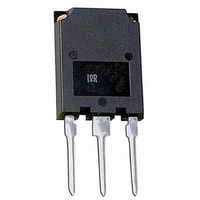
IGBT W/DIODE 1200V 99A SUPER-247

IRG4PSH71UD

Manufacturer Part Number
IRG4PSH71UD
Description
IGBT W/DIODE 1200V 99A SUPER-247
Manufacturer
International Rectifier
Datasheet

Specifications of IRG4PSH71UD

Voltage - Collector Emitter Breakdown (max)
1200V
Vce(on) (max) @ Vge, Ic
2.7V @ 15V, 70A
Current - Collector (ic) (max)
99A
Power - Max
350W
Input Type
Standard
Mounting Type
Through Hole
Package / Case
Super-247-3 (Straight Leads)
Channel Type
N
Configuration
Single
Collector-emitter Voltage
1.2kV
Gate To Emitter Voltage (max)
±20V
Pin Count
3 +Tab
Mounting
Through Hole
Operating Temperature (max)
150C
Operating Temperature Classification
Military
Package
TO-274AA
Circuit
Co-Pack
Switching
Hard
Switching Speed
ULTRAFAST 8-30 kHz
Vces (v)
1200
Ic @ 25c (a)
99
Ic @ 100c (a)
50
Vce(on)@25c Typ (v)
2.52
Vce(on)@25c Max (v)
2.70
Ets Typ (mj)
18.2
Ets Max (mj)
19.7
Vf Typ
2.92
Pd @25c (w)
350
Environmental Options
PbF
Lead Free Status / RoHS Status
Contains lead / RoHS non-compliant
Igbt Type
-
Lead Free Status / Rohs Status
Not Compliant
Other names
*IRG4PSH71UD

Available stocks

Company
Part Number
Manufacturer
Quantity
Price
Part Number:
IRG4PSH71UD
Manufacturer:
IR
Quantity:
12 500
Part Number:
IRG4PSH71UDPBF
Manufacturer:
IXYS
Quantity:
30 000
INSULATED GATE BIPOLAR TRANSISTOR WITH
ULTRAFAST SOFT RECOVERY DIODE
• UltraFast switching speed optimized for operating
• Generation 4 IGBT design provides tighter
• Industry-benchmark Super-247 package with
• Creepage distance increased to 5.35mm
Benefits
www.irf.com
Features
• Generation 4 IGBT's offer highest efficiencies
• Maximum power density, twice the power
• IGBTs optimized for specific application conditions
• Cost and space saving in designs that require
• HEXFRED
V
I
I
I
I
V
I
I
P
P
T
T
R
R
R
R
Wt
Absolute Maximum Ratings
Thermal / Mechanical Characteristics
C
C
CM
LM
F
FM
switching losses and EMI
J
STG
frequencies 8 to 40kHz in hard switching, 200kHz
in resonant mode soft switching
parameter distribution and higher efficiency
(minimum switching and conduction losses) than
CES
GE
D
D
higher power handling capability compared to
available
handling of the TO-247, less space than TO-264
multiple, paralleled IGBTs
θJC
θJC
θCS
θJA
prior generations
same footprint TO-247
@ Tc = 100°C
@ T
@ T
@ T
@ T
C
C
C
C
= 25°C
= 100°C
= 25°C
= 100°C Maximum Power Dissipation
TM
antiparallel Diode minimizes
Collector-to-Emitter Voltage
Continuous Collector Current
Pulse Collector Current
Clamped Inductive Load current
Gate-to-Emitter Voltage
Diode Continuous Forward Current
Diode Maximum Forward Current
Maximum Power Dissipation
Operating Junction and
Storage Temperature Range
Storage Temperature Range, for 10 sec.
Junction-to-Case- IGBT
Junction-to-Case- Diode
Case-to-Sink, flat, greased surface
Junction-to-Ambient, typical socket mount
Recommended Clip Force
Weight
Parameter
Parameter
d
G
n-channel
20 (2.0)
300 (0.063 in. (1.6mm) from case)
Min.
–––
–––
–––
–––
–––
IRG4PSH71UD
C
E
SUPER - 247
-55 to +150
UltraFast Copack IGBT
6 (0.21)
Max.
Typ.
1200
0.24
200
200
±20
200
350
140
–––
–––
–––
99
50
70
V
@V
CE(on) typ.
V
GE
CES
Max.
= 15V, I
0.36
0.36
–––
–––
38
PD - 91686
= 1200V
= 2.52V
C
= 50A
N (kgf)
Units
Units
g (oz.)
°C/W
°C
W
V
A
V
1

Related parts for IRG4PSH71UD

IRG4PSH71UD Summary of contents

Page 1

... G n-channel Parameter ™ d 300 (0.063 in. (1.6mm) from case) Parameter Min. ––– ––– ––– ––– 20 (2.0) ––– 91686 IRG4PSH71UD UltraFast Copack IGBT 1200V CES V = 2.52V CE(on) typ 15V 50A SUPER - 247 Max ...

Page 2

... IRG4PSH71UD Electrical Characteristics @ T Parameter Collector-to-Emitter Breakdown Voltage V (BR)CES V Emitter-to-Collector Breakdown Voltage (BR)ECS ∆V /∆T Temperature Coeff. of Breakdown Voltage (BR)CES J V Collector-to-Emitter Saturation Voltage CE(on) V Gate Threshold Voltage GE(th) ∆V /∆T Threshold Voltage temp. coefficient GE(th) J gfe Forward Transconductance I Zero Gate Voltage Collector Current ...

Page 3

... I=I RMS 1000.0 100 150°C 10.0 1.0 0 GE, Gate-to-Emitter Voltage (V) Fig Typical Transfer Characteristics IRG4PSH71UD Duty cycle : 50 125°C Tsink = 90°C Gate drive as specified Turn-on losses include effects of reverse recovery Power Dissipation = 58W 100 ) 25° 50V < ...

Page 4

... IRG4PSH71UD 100 100 Junction Temperature (°C) Fig Maximum Collector Current vs. Case Temperature 0.50 0.1 0.20 0.10 0.05 0.01 0.02 0.01 0.001 SINGLE PULSE 0.0001 ( THERMAL RESPONSE ) 1E-005 1E-006 1E-005 Fig Maximum Effective Transient Thermal Impedance, Junction-to-Case 4 4 15V 15V 380µs PULSE WIDTH 3 ...

Page 5

... Fig Typical Gate Charge vs. 1000 5.0 Ω 15V 960V 100 10 1 -60 -40 - Fig Typical Switching Losses vs. IRG4PSH71UD 100 200 300 Q G, Total Gate Charge (nC) Gate-to-Emitter Voltage 140A 70A 35A 100 120 140 160 Junction Temperature (°C) Junction Temperature 400 ...

Page 6

... IRG4PSH71UD 5.0 Ω 150° 15V 960V 100 Collector Current (A) Fig Typical Switching Losses vs. Collector-to-Emitter Current 1000 Fig Maximum Forward Voltage Drop vs. Instantaneous Forward Current 6 1000 20V 125° 100 120 140 160 100 150° 25°C 1 0.1 0.0 0.5 1.0 1.5 2.0 2.5 3.0 3.5 4.0 4.5 ...

Page 7

... 200V 125° 25°C 0 100 200 300 400 500 600 700 800 900 1000 µs) Fig Typical Stored Charge vs. di www.irf.com IRG4PSH71UD 100 140A 70A 35A 100 200 300 400 500 600 700 800 900 1000 Fig Typical Recovery Current vs. di ...

Page 8

... IRG4PSH71UD Same type device as D.U.T. 430µF 80% of Vce Fig. 18a - Test Circuit for Measurement off(diode d(on) GATE VOLTAGE D.U.T. 10% +Vg +Vg Vce 10% Ic Vcc 90 Vce tr td(on) t1 Fig. 18c - Test Waveforms for Circuit of Fig. 18a, Defining d(on 90% D.U.T. 10 d(on d(off) f Fig. 18b - Test Waveforms for Circuit of Fig ...

Page 9

... Figure 18e. Macro Waveforms for L 1000V 50V 6000µF 100V Figure 19. Clamped Inductive Load Test Circuit www.irf.com Vg GATE SIGNAL DEVICE UNDER TEST CURRENT D.U.T. VOLTAGE IN D.U.T. CURRENT Figure 18a's D.U. Figure 20. Pulsed Collector Current IRG4PSH71UD Test Circuit L C Test Circuit 9 ...

Page 10

... IRG4PSH71UD Super-247™ (TO-274AA) Package Outline 16.10 [.632] A 15.10 [.595] 3.00 [.118 2.00 [.079] 20.80 [.818] 19.80 [.780 14.80 [.582] 4.25 [.167] 13.80 [.544] 3.85 [.152] 1.60 [.062] 3X 1.45 [.058] 5.45 [.215] 2X 0.25 [.010] Super-247™ (TO-274AA) Part Marking Information EXAMPLE: THIS IS AN IRFPS37N50A WITH ...

Related keywords