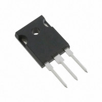
IRGPH40F International Rectifier, IRGPH40F Datasheet

IRGPH40F
Specifications of IRGPH40F
Available stocks
Related parts for IRGPH40F
IRGPH40F Summary of contents
Page 1
... T Storage Temperature Range STG Soldering Temperature, for 10 sec. Mounting torque, 6- screw. Thermal Resistance Parameter R Junction-to-Case JC R Case-to-Sink, flat, greased surface CS R Junction-to-Ambient, typical socket mount JA Wt Weight IRGPH40F Fast Speed IGBT n-channel Max. 1200 ±20 15 160 65 -55 to +150 300 (0.063 in. (1.6mm) from case) 10 lbf• ...
Page 2
... IRGPH40F Electrical Characteristics @ T Parameter V Collector-to-Emitter Breakdown Voltage (BR)CES V Emitter-to-Collector Breakdown Voltage (BR)ECS Temperature Coeff. of Breakdown Voltage (BR)CES J V Collector-to-Emitter Saturation Voltage CE(on) V Gate Threshold Voltage GE(th Temperature Coeff. of Threshold Voltage GE(th Forward Transconductance fe I Zero Gate Voltage Collector Current CES I Gate-to-Emitter Leakage Current ...
Page 3
... G ate drive as spec ifie d Pow er D issipation = 35W quency ( fundamental; for triangular wave, I=I RMS 1000 100 0° ° 0.1 0. Fig Typical Transfer Characteristics C-275 IRGPH40F Tria ngular w ave: C lam p voltage: 80% of rated 100 ) µ ate- itter V o lta ...
Page 4
... IRGPH40F 100 ase Tem perature (° Fig Maximum Collector Current vs. Case Temperature 0.2 0 0.1 0 .05 SIN ( 0.0 2 0.0 1 0.01 0.00001 0.0001 Fig Maximum Effective Transient Thermal Impedance, Junction-to-Case 5 0µ IDTH 4.0 3.0 2.0 -60 -40 -20 125 150 ture (°C ) Fig Collector-to-Emitter Voltage vs. ...
Page 5
... Fig Typical Capacitance vs. Collector-to-Emitter Voltage 25° ate R es istance ( ) G Fig Typical Switching Losses vs. Gate Resistance SHORTED Fig Typical Gate Charge vs. 100 0 -60 -40 W Fig Typical Switching Losses vs. C-277 IRGPH40F = tal Gate-to-Emitter Voltage = 8 - 100 120 140 160 ase Tem perature (° Case Temperature 5 0 ...
Page 6
... IRGPH40F 50° lle itte rre Fig Typical Switching Losses vs. Collector-to-Emitter Current Refer to Section D for the following: Appendix G: Section D - page D-9 Fig. 13a - Clamped Inductive Load Test Circuit Fig. 13b - Pulsed Collector Current Test Circuit Fig. 14a - Switching Loss Test Circuit Fig ...
Page 7
Note: For the most current drawings please refer to the IR website at: http://www.irf.com/package/ ...


