IXEL40N400 IXYS, IXEL40N400 Datasheet

IGBT 4000V SINGLE ISOPLUS I5

IXEL40N400

Manufacturer Part Number
IXEL40N400
Description
IGBT 4000V SINGLE ISOPLUS I5
Manufacturer
IXYS
Datasheet

Specifications of IXEL40N400

Voltage - Collector Emitter Breakdown (max)
4000V
Vce(on) (max) @ Vge, Ic
3.5V @ 15V, 40A
Current - Collector (ic) (max)
40A
Power - Max
380W
Input Type
Standard
Mounting Type
Through Hole
Package / Case
ISOPLUSi5-Pak™
Channel Type
N
Configuration
Single
Collector Current (dc) (max)
40A
Gate To Emitter Voltage (max)
±20V
Pin Count
3
Mounting
Through Hole
Operating Temperature (min)
-40C
Operating Temperature Classification
Automotive
Vces, (v)
4000
Ic25, Tc=25°c, Igbt, (a)
-
Ic110, Tc=110°c, Igbt, (a)
-
Vce(sat), Max, Tj=25°c, Igbt, (v)
3.5
Tfi, Typ, Igbt, (ns)
425
Eoff, Typ, Tj=125°c, Igbt, (mj)
205
Tf, Typ, Igbt, (ns)
-
Rthjc, Max, Igbt, (k/w)
0.26
Package Style
ISOPLUS264
Lead Free Status / RoHS Status
Lead free / RoHS Compliant
Igbt Type
-
Lead Free Status / RoHS Status
Compliant, Lead free / RoHS Compliant

Available stocks

Company
Part Number
Manufacturer
Quantity
Price
Part Number:
IXEL40N400
Manufacturer:
CIRRUS
Quantity:
1 001
Very High Voltage
IGBT
( Electrically Isolated Tab)
Symbol
V
V
V
I
I
P
T
T
T
T
T
V
F
Weight
Symbol
(T
V
I
I
V
© 2009 IXYS CORPORATION, All Rights Reserved
C90
CM
CES
GES
J
JM
stg
L
SOLD
C
CES
GES
GEM
C
ISOL
GE(th)
CE(sat)
J
= 25°C, Unless Otherwise Specified)
Test Conditions
T
Continuous
Transient
T
Pulse Width Limited by T
T
Maximum Lead Temperature for Soldering
1.6 mm (0.062 in.) from Case for 10s
I
Mounting Force
Test Conditions
I
V
V
I
ISOL
C
C
J
C
C
CE
CE
= 25°C to 125°C
= 90°C
= 25°C
< 1mA, 50/60 Hz, t = 1 minute
= 10mA, V
= V
= 0V, V
= I
C90
CES
, V
, V
GE
GE
GE
= ±20V
CE
= 15V, Note 1
= 0V
= V
GE
Note 2, T
JM
, 1ms, V
Preliminary Technical Information
T
J
J
= 125°C
= 125°C
GE
= 20V
IXEL40N400
30..170 / 7..36
5.5
Min.
Characteristic Values
- 40 ... +125
- 40 ... +125
Maximum Ratings
4000
4000
Typ.
300
260
±20
±30
380
125
250
1.5
3.0
40
2.5
8
±500
100
Nm/lb-in.
7.0
3.5
Max.
mA
V~
μA
nA
°C
°C
°C
°C
°C
W
V
V
V
A
A
V
V
V
g
V
I
V
t
ISOPLUS i5-Pak
G = Gate
E = Emitter
Features
Advantages
Applications
C90
fi(typ)
Silicon Chip on Direct-Copper Bond
(DCB) Substrate
Isolated Mounting Surface
4000V Electrical Isolation
UL Recognized Package
High Peak Current Capability
Low Saturation Voltage
Molding Epoxies Meet UL 94 V-0
Flammability Classification
High Power Density
Easy to Mount
Capacitor Discharge
Pulser Circuits
CES
CE(sat)
G
E
C
≤ ≤ ≤ ≤ ≤
=
=
=
C = Collector
TM
3.5V
40A
425ns
4000V
Isolated Tab
DS99385A(12/09)

Related parts for IXEL40N400

IXEL40N400 Summary of contents

Page 1

... CES CE CES 0V ±20V GES 15V, Note 1 CE(sat) C C90 GE © 2009 IXYS CORPORATION, All Rights Reserved Preliminary Technical Information IXEL40N400 Maximum Ratings 4000 ±20 ± 1ms 20V 250 JM GE 380 - 40 ... +125 125 - 40 ... +125 300 260 4000 30..170 / 7..36 8 Characteristic Values Min. Typ. ...

Page 2

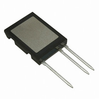
... T CE 4,931,844 5,049,961 5,237,481 6,162,665 5,017,508 5,063,307 5,381,025 6,259,123 B1 5,034,796 5,187,117 5,486,715 6,306,728 B1 IXEL40N400 ISOPLUS i5-Pak Max Ω Pin 1 = Gate Pin 2 = Emitter nC Pin 3 = Collector Tab 4 = Isolated nC SYM INCHES MIN MAX nC A ...

Page 3

... 25V GE 19V 15V 13V 11V 9V 7V 3.0 3.5 4.0 4.5 5 25º IXEL40N400 Fig. 2. Extended Output Characteristics @ 25V GE 21V 19V 17V 15V 13V 11V Volts CE Fig. 4. Dependence of V Junction Temperature 2 15V GE 1.8 I ...

Page 4

... IXYS Reserves the Right to Change Limits, Test Conditions, and Dimensions 100,000 10,000 1,000 100 10 160 200 240 280 Fig. 11. Maximum Transient Thermal Impedance 0.001 0.01 Pulse Width - Seconds IXEL40N400 Fig. 8. Transconductance 40ºC J 25ºC 125º 100 120 I - Amperes C Fig. 10. Capacitance MHz Volts CE 0.1 1 ...

Related keywords