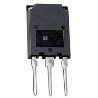
IRGPS40B120UPBF International Rectifier, IRGPS40B120UPBF Datasheet - Page 7

IRGPS40B120UPBF
Manufacturer Part Number
IRGPS40B120UPBF
Description
IGBT ULT FAST 1200V 80A SUPER247
Manufacturer
International Rectifier
Datasheet
1.IRGPS40B120UPBF.pdf
(10 pages)
Specifications of IRGPS40B120UPBF
Igbt Type
NPT
Voltage - Collector Emitter Breakdown (max)
1200V
Vce(on) (max) @ Vge, Ic
3.71V @ 15V, 50A
Current - Collector (ic) (max)
80A
Power - Max
595W
Input Type
Standard
Mounting Type
Through Hole
Package / Case
Super-247-3 (Straight Leads)
Channel Type
N
Configuration
Single
Collector-emitter Voltage
1.2kV
Collector Current (dc) (max)
80A
Gate To Emitter Voltage (max)
±20V
Pin Count
3 +Tab
Mounting
Through Hole
Operating Temperature (min)
-55
Operating Temperature (max)
150C
Operating Temperature Classification
Military
Transistor Type
IGBT
Dc Collector Current
80A
Collector Emitter Voltage Vces
3.5V
Power Dissipation Pd
595W
Collector Emitter Voltage V(br)ceo
1.2kV
Transistor Case Style
TO-274AA
No. Of Pins
3
Rohs Compliant
Yes
Operating Temperature Range
-55°C To +150°C
Lead Free Status / RoHS Status
Lead free / RoHS Compliant
Other names
*IRGPS40B120UPBF
Available stocks
Company
Part Number
Manufacturer
Quantity
Price
www.irf.com
10000
0.01
1000
0.1
100
10
10
1
1E-005
Fig. 16- Typ. Capacitance vs. V
0
D = 0.50
Fig 18. Normalized Transient Thermal Impedance, Junction-to-Case (IGBT)
0.05
0.01
0.02
0.10
0.20
V
20
GE
= 0V; f = 1MHz
40
0.0001
V CE (V)
SINGLE PULSE
( THERMAL RESPONSE )
60
Cies
Coes
Cres
t 1 , Rectangular Pulse Duration (sec)
CE
80
0.001
100
Fig. 17 - Typical Gate Charge vs. V
16
14
12
10
8
6
4
2
0
0
0.01
IRGPS40B120UP
50
I
CE
Q G , Total Gate Charge (nC)
100 150 200 250 300 350 400
= 40A; L = 600µH
Notes:
1. Duty Factor D = t1/t2
2. Peak Tj = P dm x Zthjc + Tc
0.1
600V
800V
GE
7
1


