STPS1045B Vishay, STPS1045B Datasheet - Page 2
STPS1045B
Manufacturer Part Number
STPS1045B
Description
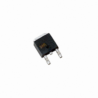
DIODE SCHOTTKY 45V 10A D-PAK
Manufacturer
Vishay
Specifications of STPS1045B
Voltage - Forward (vf) (max) @ If
630mV @ 10A
Voltage - Dc Reverse (vr) (max)
45V
Current - Average Rectified (io)
10A
Current - Reverse Leakage @ Vr
200µA @ 45V
Diode Type
Schottky
Speed
Fast Recovery =< 500ns, > 200mA (Io)
Mounting Type
Surface Mount
Package / Case
DPak, TO-252 (2 leads+tab), SC-63
Product
Schottky Rectifiers
Peak Reverse Voltage
45 V
Forward Continuous Current
10 A
Max Surge Current
390 A
Configuration
Single Dual Anode
Forward Voltage Drop
0.63 V
Maximum Reverse Leakage Current
200 uA
Operating Temperature Range
- 40 C to + 175 C
Mounting Style
SMD/SMT
Lead Free Status / RoHS Status
Contains lead / RoHS non-compliant
Reverse Recovery Time (trr)
-
Capacitance @ Vr, F
-
Lead Free Status / RoHS Status
Contains lead / RoHS non-compliant, Lead free / RoHS Compliant
Other names
*STPS1045B
STPS1045B
STPS1045BIR
VS-STPS1045B
VS-STPS1045BIR
VS-STPS1045BIR
VSSTPS1045B
VSSTPS1045BIR
STPS1045B
STPS1045BIR
VS-STPS1045B
VS-STPS1045BIR
VS-STPS1045BIR
VSSTPS1045B
VSSTPS1045BIR
Available stocks
Company
Part Number
Manufacturer
Quantity
Price

Part Number:
STPS1045B
Manufacturer:
ST
Quantity:
20 000
Part Number:
STPS1045BTRL-M3
Manufacturer:
VISHAY/威世
Quantity:
20 000
Part Number:
STPS1045BY-TR
Manufacturer:
ST
Quantity:
20 000


VS-STPS1045BPbF
Vishay Semiconductors
Note
(1)
Note
(1)
www.vishay.com
2
ELECTRICAL SPECIFICATIONS
PARAMETER
Maximum forward voltage drop
See fig. 1
Maximum reverse leakage current
See fig. 2
Typical junction capacitance
Typical series inductance
Maximum voltage rate of change
THERMAL - MECHANICAL SPECIFICATIONS
PARAMETER
Maximum junction and storage
temperature range
Maximum thermal resistance,
junction to case
Maximum thermal resistance,
junction to ambient
Approximate weight
Marking device
Pulse width < 300 μs, duty cycle < 2 %
dP
------------ -
dT
tot
J
<
------------- -
R
thJA
1
thermal runaway condition for a diode on its own heatsink
DiodesAmericas@vishay.com, DiodesAsia@vishay.com,
For technical questions within your region, please contact one of the following:
SYMBOL
SYMBOL
T
J
V
I
dV/dt
R
R
RM
(1)
FM
Schottky Rectifier, 10 A
C
L
thJC
thJA
, T
S
T
(1)
(1)
Stg
10 A
20 A
10 A
20 A
T
T
V
Measured lead to lead 5 mm from package body
Rated V
DC operation
See fig. 4
Case style D-PAK (similar to TO-252AA)
J
J
R
= 25 °C
= 125 °C
= 5 V
R
DC
(test signal range 100 kHz to 1 MHz), 25 °C
TEST CONDITIONS
TEST CONDITIONS
DiodesEurope@vishay.com
T
T
V
J
J
R
= 25 °C
= 125 °C
= Rated V
R
Document Number: 94323
- 40 to 175
VALUES
VALUES
10 000
0.01
0.63
0.84
0.57
0.72
760
Revision: 14-Jan-11
3.0
0.3
0.2
5.0
15
50
STPS1045B
UNITS
UNITS
°C/W
V/μs
mA
oz.
nH
pF
°C
V
g
Related parts for STPS1045B
Image
Part Number
Description
Manufacturer
Datasheet
Request
R

Part Number:
Description:
357-036-542-201 CARDEDGE 36POS DL .156 BLK LOPRO
Manufacturer:
Vishay
Datasheet:
Part Number:
Description:
357-036-542-201 CARDEDGE 36POS DL .156 BLK LOPRO
Manufacturer:
Vishay
Datasheet:
Part Number:
Description:
357-036-542-201 CARDEDGE 36POS DL .156 BLK LOPRO
Manufacturer:
Vishay
Datasheet:
Part Number:
Description:
357-036-542-201 CARDEDGE 36POS DL .156 BLK LOPRO
Manufacturer:
Vishay
Datasheet:
Part Number:
Description:
357-036-542-201 CARDEDGE 36POS DL .156 BLK LOPRO
Manufacturer:
Vishay
Datasheet:
Part Number:
Description:
357-036-542-201 CARDEDGE 36POS DL .156 BLK LOPRO
Manufacturer:
Vishay
Datasheet:
Part Number:
Description:
357-036-542-201 CARDEDGE 36POS DL .156 BLK LOPRO
Manufacturer:
Vishay
Datasheet:
Part Number:
Description:
357-036-542-201 CARDEDGE 36POS DL .156 BLK LOPRO
Manufacturer:
Vishay
Datasheet:
Part Number:
Description:
357-036-542-201 CARDEDGE 36POS DL .156 BLK LOPRO
Manufacturer:
Vishay
Datasheet:
Part Number:
Description:
357-036-542-201 CARDEDGE 36POS DL .156 BLK LOPRO
Manufacturer:
Vishay
Datasheet:
Part Number:
Description:
357-036-542-201 CARDEDGE 36POS DL .156 BLK LOPRO
Manufacturer:
Vishay
Datasheet:
Part Number:
Description:
357-036-542-201 CARDEDGE 36POS DL .156 BLK LOPRO
Manufacturer:
Vishay
Datasheet:
Part Number:
Description:
357-036-542-201 CARDEDGE 36POS DL .156 BLK LOPRO
Manufacturer:
Vishay
Datasheet:
Part Number:
Description:
357-036-542-201 CARDEDGE 36POS DL .156 BLK LOPRO
Manufacturer:
Vishay
Datasheet:
Part Number:
Description:
357-036-542-201 CARDEDGE 36POS DL .156 BLK LOPRO
Manufacturer:
Vishay
Datasheet: