HFA25TB60STRL Vishay, HFA25TB60STRL Datasheet
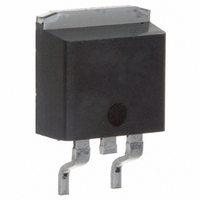
DIODE HEXFRED 600V 25A D2PAK

HFA25TB60STRL

Manufacturer Part Number
HFA25TB60STRL
Description
DIODE HEXFRED 600V 25A D2PAK
Manufacturer
Vishay
Series
HEXFRED®r
Datasheet

Specifications of HFA25TB60STRL

Voltage - Forward (vf) (max) @ If
1.7V @ 25A
Voltage - Dc Reverse (vr) (max)
600V
Current - Average Rectified (io)
25A
Current - Reverse Leakage @ Vr
20µA @ 600V
Diode Type
Standard
Speed
Fast Recovery =< 500ns, > 200mA (Io)
Reverse Recovery Time (trr)
75ns
Mounting Type
Surface Mount
Package / Case
D²Pak, TO-263 (2 leads + tab)
Lead Free Status / RoHS Status
Contains lead / RoHS non-compliant
Capacitance @ Vr, F
-
Document Number: 93086
HEXFRED
• Ultrafast Recovery
• Ultrasoft Recovery
• Very Low
• Very Low
• Specified at Operating Conditions
• Reduced RFI and EMI
• Reduced Power Loss in Diode and Switching
• Higher Frequency Operation
• Reduced Snubbing
• Reduced Parts Count
Absolute Maximum Ratings
* 125°C
V
I
I
I
P
P
T
T
F
FSM
FRM
J
STG
Features
Benefits
Transistor
D
D
Description
International Rectifier's HFA25TB60S is a state of the art ultra fast recovery
diode. Employing the latest in epitaxial construction and advanced processing
techniques it features a superb combination of characteristics which result in
performance which is unsurpassed by any rectifier previously available. With
basic ratings of 600 volts and 25 amps continuous current, the HFA25TB60S
is especially well suited for use as the companion diode for IGBTs and
MOSFETs. In addition to ultra fast recovery time, the HEXFRED product line
features extremely low values of peak recovery current (I
exhibit any tendency to "snap-off" during the t
HEXFRED features combine to offer designers a rectifier with lower noise and
significantly lower switching losses in both the diode and the switching
transistor. These HEXFRED advantages can help to significantly reduce
snubbing, component count and heatsink sizes. The HEXFRED HFA25TB60S is
ideally suited for applications in power supplies and power conversion systems
(such as inverters), motor drives, and many other similar applications where
high speed, high efficiency is needed.
R
@ T
@ T
@ T
C
C
C
= 100°C
= 25°C
= 100°C
I
Q
RRM
rr
TM
Cathode-to-Anode Voltage
Continuous Forward Current
Single Pulse Forward Current
Maximum Repetitive Forward Current
Maximum Power Dissipation
Operating Junction and
Storage Temperature Range
Parameter
b
portion of recovery.
N/C
RRM
1
Cathode
) and does not
Base
2
Bulletin PD-20616 rev. B 11/03
Ultrafast, Soft Recovery Diode
Anode
3
HFA25TB60S
The
-55 to +150
Max.
600
225
100
125
25
50
di
(rec)M
Q
V
t
rr
rr
F
/dt (typ.) = 250A/µs
I
I
V
(typ.)* = 1.3V
(typ.) = 23ns
F(AV)
(typ.)= 112nC
RRM
D
R
2
= 600V
www.vishay.com
= 10A
Pak
= 25A
Units
V
A
W
°C
1

Related parts for HFA25TB60STRL

HFA25TB60STRL Summary of contents

Page 1

... Ultrafast, Soft Recovery Diode Base Cathode N/C Anode (rec)M ) and does not RRM portion of recovery. The b Max. 600 25 225 100 125 50 -55 to +150 V = 600V R V (typ.)* = 1. 25A F(AV) Q (typ.)= 112nC 10A RRM t (typ.) = 23ns rr /dt (typ.) = 250A/µ Pak Units °C www.vishay.com 1 ...

Page 2

... V = 200V 25° 125°C di /dt = 200A/µ 25° 125°C J Typ. Max. Units –––– 300 °C –––– 1.0 K/W –––– 80 2.0 –––– g 0.07 –––– (oz) www.vishay.com 2 ...

Page 3

... Fig Typical Reverse Current vs. Reverse A 1000 100 A 2.6 ( Reverse Voltage - V (V) Fig Typical Junction Capacitance vs. Notes: 1. Duty factor Peak 0.001 0. Rectangular Pulse Duration (sec) 1 Characteristics thjc HFA25TB60S A 200 300 400 500 600 (V) R Voltage T = 25° 100 1000 R Reverse Voltage thJC C 0.1 1 www.vishay.com 3 ...

Page 4

... Document Number: 93086 200V 125° 25° 50A 25A 10A 1000 100 Fig Typical Recovery Current vs. di /dt f 10000 V = 200V 125° 25° 50A F 1000 I = 25A 10A F A 100 1000 100 /dt Fig Typical 1000 di /dt - (A/µ 1000 di /dt - (A/µs) f /dt vs. di /dt (rec)M f www.vishay.com 4 ...

Page 5

... F through 0.75 I and 0.50 I RRM extrapolated to zero current Fig Reverse Recovery Waveform and HFA25TB60S 0.5 I RRM RRM di(rec)M/dt 5 0.75 I RRM Area under curve defined and I RRM RRM /dt - Peak rate of change of (rec)M current during t portion RRM Definitions www.vishay.com 5 ...

Page 6

... MAX. 5.08 (0.20) REF. 3.81 (0.15) 2.08 (0.08 Conforms to JEDEC Outline D PAK (K) HFA25TB60S 9712 5K3A ASSEMBLY LOT CODE (N/C) (A) 17.78 (0.70) 2.54 (0.10) 2X PART NUMBER DATE CODE (YYWW YEAR WW = WEEK www.vishay.com 6 ...

Page 7

... SMD-220 Tape & Reel When ordering, indic ate the part number, part orientation, and the quantity. Quantities are in multiples of 800 pieces per reel for both TRL and TRR. TAC Fax: (310) 252-7309 11/03 www.vishay.com 7 ...

Page 8

... Except as provided in Vishay's terms and conditions of sale for such products, Vishay assumes no liability whatsoever, and disclaims any express or implied warranty, relating to sale and/or use of Vishay products including liability or warranties relating to fitness for a particular purpose, merchantability, or infringement of any patent, copyright, or other intellectual property right. ...

Related keywords