P9EA-C Omron, P9EA-C Datasheet - Page 4
P9EA-C
Manufacturer Part Number
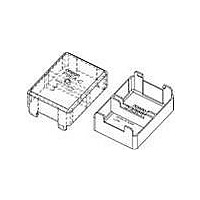
P9EA-C
Description
TERMINAL COVER FOR G9EA
Manufacturer
Omron
Series
G9EA-1r
Datasheet
1.P9EA-C.pdf
(7 pages)
Specifications of P9EA-C
Accessory Type
Cover, Terminal
Associated Relay Series
G9EA-1
Width
36 mm
Rohs Compliant
Yes
Lead Free Status / RoHS Status
Lead free / RoHS Compliant
For Use With/related Products
G9EA-1 Series
For Use With
G9EA-1DC60 - RELAY DC IND SPST 60VDCG9EA-1DC48 - RELAY DC IND SPST 48VDCG9EA-1DC100 - RELAY DC IND SPST 100VDCG9EA-1-CADC48 - RELAY DC IND SPST 48VDCG9EA-1-CADC100 - RELAY DC IND SPST 100VDCG9EA-1-BDC60 - RELAY DC IND SPST 60VDCG9EA-1-BDC48 - RELAY DC IND SPST 48VDCG9EA-1-BDC100 - RELAY DC IND SPST 100VDCG9EA-1-B-CADC60 - RELAY DC IND SPST 60VDCG9EA-1-B-CADC48 - RELAY DC IND SPST 48VDCG9EA-1-B-CADC100 - RELAY DC IND SPST 100VDCZ1617 - RELAY IND SPST 100ADC SCREW TERMZ1616 - RELAY IND SPST 100ADC SCREW TERMZ1615 - RELAY IND SPST 100ADC LEAD TERMZ1614 - RELAY IND SPST 100ADC LEAD TERMZ1613 - RELAY IND SPST 60ADC LEAD TERMZ1612 - RELAY IND SPST 60ADC LEAD TERMZ1611 - RELAY IND SPST 60ADC SCREW TERMZ1610 - RELAY IND SPST 60ADC SCREW TERM
Color
-
Lead Free Status / Rohs Status
Lead free / RoHS Compliant
Other names
P9EAC


■ All G9EA-1 Models
8
−10.0
10.0
−2.0
−4.0
−6.0
−8.0
30
25
20
15
10
8.0
6.0
4.0
2.0
0.0
5
0
Must-operate Voltage and
Must-release Voltage
Distributions
Characteristics were measured after applying vibration
at a frequency of 10 to 55 Hz (single amplitude of 0.75
mm) to the test piece (not energized) for 2 hours each
in 3 directions. The percentage rate of change is the
average value for all of the samples
Vibration Resistance
Start
Sample: G9EA-1
Number: 35
Sample: G9EA-1
Number: 5
20
DC Power Relays (60-A, 100-A Models)
40
Percentage of rated voltage (%)
Must-operate voltage
Must-release voltage
60
Must-release voltage
Must-operate voltage
80
After test
100
20
15
10
5
0
Shock Malfunction
Unit: m/s
Sample: G9EA-1
Number: 5
X
Z'
Time Characteristic
Distributions
The value at which malfunction occurred was
measured after applying shock to the test piece
3 times each in 6 directions along 3 axes.
5.0
Deenergized
2
Sample: G9EA-1
Number: 35
10.0
G9EA-1
Y
Y'
800
600
400
200
200
400
600
800
1,000
1,000
15.0
20.0
Y'
Energized
Y X'
Operate time
Release time
Y
25.0
Time (ms)
Z
X'
X
Z'
Z
30.0
−10.0
10.0
−2.0
−4.0
−6.0
−8.0
0.9
0.8
0.7
0.6
0.5
0.4
0.3
0.2
0.1
8.0
6.0
4.0
2.0
0.0
1
0
Vibration Malfunction
1
Characteristics were measured
of 490 m
along 3 axes
average value for all of the samples.
Shock Resistance
Start
Sample: G9EA-1
Number: 5
Sample: G9EA-1
Number: 5
2
/s to the test piece 3 times each in 6 directions
3
. The percentage rate of change is the
5
10
Unconfirmed area
Confirmed area
Must-operate voltage
Must-release voltage
after applying a shock
Frequency (Hz)
30
50
After test
100
Related parts for P9EA-C
Image
Part Number
Description
Manufacturer
Datasheet
Request
R

Part Number:
Description:
Din Rail Adapter For G9EA
Manufacturer:
Omron
Datasheet:

Part Number:
Description:
G6S-2GLow Signal Relay
Manufacturer:
Omron Corporation
Datasheet:
Part Number:
Description:
Compact, Low-cost, SSR Switching 5 to 20 A
Manufacturer:
Omron Corporation
Datasheet:
Part Number:
Description:
Manufacturer:
Omron Corporation
Datasheet:
Part Number:
Description:
Manufacturer:
Omron Corporation
Datasheet:
Part Number:
Description:
Manufacturer:
Omron Corporation
Datasheet:
Part Number:
Description:
Manufacturer:
Omron Corporation
Datasheet:
Part Number:
Description:
Manufacturer:
Omron Corporation
Datasheet:
Part Number:
Description:
Manufacturer:
Omron Corporation
Datasheet: