G9YA-12S-45 DC24 Omron, G9YA-12S-45 DC24 Datasheet - Page 8
G9YA-12S-45 DC24
Manufacturer Part Number
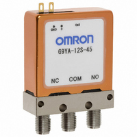
G9YA-12S-45 DC24
Description
HF RELAY
Manufacturer
Omron
Series
G9YAr
Datasheet
1.G9YA-12S-45_DC4.5.pdf
(10 pages)
Specifications of G9YA-12S-45 DC24
Relay Type
RF
Contact Form
SPDT (1 Form C)
Coil Type
Standard
Coil Current
29.2mA
Coil Voltage
24VDC
Turn On Voltage (max)
19.2 VDC
Turn Off Voltage (min)
2.4 VDC
Mounting Type
Chassis Mount
Termination Style
Solder Lug
Circuit
SPDT (1 Form C)
Control On Voltage (max)
19.2 VDC
Control Off Voltage (min)
2.4 VDC
Lead Free Status / RoHS Status
Lead free / RoHS Compliant
Contact Rating @ Voltage
-
Lead Free Status / RoHS Status
Lead free / RoHS Compliant
Other names
G9YA12S45DC24
Z2512
Z2512


Precautions
■ Precautions for Correct Use
Relay Handling
• Relays are precision components. Do not subject the Relay to
• Avoid subjecting the Relay to direct sunlight when it is being used,
• The Relay is not sealed. It cannot be washed.
• Be absolutely sure not to wire the Relay incorrectly. Incorrect wiring
• Recommended torque for mounting the SMA connectors is the
• Use of two or more Relays may result in change in the Relay char-
• Use a power supply for the coil operating power supply with a max-
• Operation in excess of the coil ratings, contact ratings, switching
Latching Relay Mounting
Make sure that the vibration or shock generated from other devices
(e.g., Relays) on the same panel during operation or resetting do not
exceed the values provided in the catalog, otherwise the latching
Relay that has been set may be reset or vice versa. The latching
Relay is reset before shipping. If excessive vibration or shock is
imposed, however, the latching Relay may be set accidentally. Be
sure to apply a reset signal before use.
Long-term Continuously ON Contacts
Using the Relay in a circuit where the Relay will be ON continuously
for long periods (without switching) can lead to unstable contacts
because the heat generated by the coil itself will deteriorate the insu-
lation, causing a film to develop on the contact surfaces. We recom-
mend using a latching Relay (magnetic-holding Relay) in this kind of
circuit. If a failsafe Relay must be used in this kind of circuit, use a
full-loop circuit design to provide protection against possible poor
connections and coil disconnection.
364
vibration or shock in excess of the standard values, whether before
or after mounting. The original performance cannot be maintained if
the Relay is subjected to abnormal vibration or shock or dropped.
Also, do not subject the Relay to vibration or shock in excess of the
rated values when it is still packaged.
stored or transported. Keep the Relay at conditions of normal tem-
perature, humidity, and pressure.
will result in failure of Relay functions and damage or fire in the
Relay, in addition to affecting external circuits.
MIL-C-39012 standard of 0.90±0.1 N·m. The conditions, however,
depend on the compatibility with the material of the connectors.
acteristics due to interference in the magnetic fields generated by
the Relays. Be sure to check operation using the actual devices
before use.
imum ripple of 5%. Be sure to check operation using the actual
devices before use.
service life or other specifications may result in abnormal heat gen-
eration, smoke, or fire.
Coaxial Switch
G9YA
DISCONTINUED
Using Relays in an Atmosphere Containing
Corrosive Gas (Silicon, Sulfuric, or Organic Gas)
Do not use Relays in a location where silicon gas, sulfuric gas
(SO
period in an atmosphere of sulfuric gas or organic gas, contact sur-
faces may become corroded and cause contact instability and
obstruction, and terminal soldering characteristics may be degraded.
If Relays are stored or used for a long time in an atmosphere of sili-
con gas, a silicon coating will be generated on contact surfaces,
causing contact failure.
Connecting to Coil and Indicator Terminals
I. Models with Soldering Terminals
Perform manual soldering under the following conditions.
II. Models with Pin Terminals
Heed the following precautions when using models with pin terminals.
1. Connectors for use: Straight dip type for panels
2. The sockets do not have a lock mechanism. Pulling the lead
3. Do not solder the lead wires directly to the pin connectors.
Soldering iron tip temperature: 280 to 300°C
Soldering time: Approx. 3 s max.
Male connectors: HKP-8M29 (Honda Tsushin Kogyo)
Refer to the general catalog of Honda Tsushin Kogyo for connec-
tor models and specifications.
wires, shock, or long-term vibration may cause the connectors to
become disconnected. Heed the following precautions.
• Securely fix the Relay and connectors and make sure that no
• Fully insert the socket into the Relay connector.
2
, H
force is pulling on the lead wires during use.
2
S), or organic gas is present. If Relays are used for a long
Related parts for G9YA-12S-45 DC24
Image
Part Number
Description
Manufacturer
Datasheet
Request
R

Part Number:
Description:
HF RELAY
Manufacturer:
Omron
Datasheet:
Part Number:
Description:
HF RELAY
Manufacturer:
Omron
Datasheet:
Part Number:
Description:
HF RELAY
Manufacturer:
Omron
Datasheet:
Part Number:
Description:
HF RELAY
Manufacturer:
Omron
Datasheet:

Part Number:
Description:
HF RELAY
Manufacturer:
Omron
Datasheet:
Part Number:
Description:
HF RELAY
Manufacturer:
Omron
Datasheet:
Part Number:
Description:
Coaxial Switches 26.5 GHz Coax HF Relay
Manufacturer:
Omron

Part Number:
Description:
G6S-2GLow Signal Relay
Manufacturer:
Omron Corporation
Datasheet:
Part Number:
Description:
Compact, Low-cost, SSR Switching 5 to 20 A
Manufacturer:
Omron Corporation
Datasheet:
Part Number:
Description:
Manufacturer:
Omron Corporation
Datasheet: