E3S-AR36 Omron, E3S-AR36 Datasheet - Page 25
E3S-AR36
Manufacturer Part Number
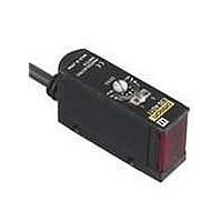
E3S-AR36
Description
2M RETRO PNP W/CONN HOR
Manufacturer
Omron
Type
Photoelectric Sensorr
Series
E3S-Ar
Specifications of E3S-AR36
Features
Light ON / Dark ON
Height
22.3 mm
Length
52.3 mm
Maximum Operating Temperature
+ 55 C
Minimum Operating Temperature
- 25 C
Operating Supply Voltage
10 V to 30 V
Width
12.4 mm
Sensing Distance
2000 mm
Output Configuration
PNP
Svhc
No SVHC (15-Dec-2010)
Output Type
PNP
Response Time
0.5ms
Sensing Range Max
2m
Supply Voltage Dc Max
30V
Connector Type
M12 Screw Connector
Current Consumption
30mA
External Depth
52.3mm
Rohs Compliant
Yes
External Length / Height
22.3mm
External Width
12.4mm
Ip/nema Rating
IP67
Sensing Method
Retroreflective
Sensing Object
Mirror
Sensing Light
Red
Mounting Type
Chassis Mount
Current - Supply
30mA
Voltage - Supply
10 V ~ 30 V
Package / Case
Module, Connector
Lead Free Status / RoHS Status
Lead free / RoHS Compliant
Lead Free Status / RoHS Status
Lead free / RoHS Compliant
Available stocks
Company
Part Number
Manufacturer
Quantity
Price
Company:

Part Number:
E3S-AR36
Manufacturer:
OMRON
Quantity:
1 000


Securing Fibers
The E3X Fiber Unit uses a one-touch locking mechanism. Use the
following methods to attach and remove Fiber Units.
(1) Attaching Fibers
Open the protective cover, insert the fiber up to the insertion mark on
the side of the Fiber Unit, and then lower the lock lever.
(2) Removing Fibers
Open the protective cover, lift up the lock lever, and pull out the fibers.
Note:1.To maintain the fiber characteristics, make sure that the lock
Lock lever
Fiber
2. Lock and unlock the fibers at an ambient temperature of
is released before removing the fibers.
−
Fiber insertion mark
10 to 40°C.
Locked position
http://www.ia.omron.com/
Lock released
position
Locked
position
9mm
Protective cover
Insertion
position
Lock released position
Protective cover
Photoelectric Sensors Technical Guide
● Adjustments
Optical Axis Adjustment
Move the Photoelectric Sensor both vertically and horizontally and set
it in the center of the range in which the operation indicator is lit or not
lit. For the E3S-C, the optical axis and the mechanical axis are the
same, so the optical axis can be easily adjusted by aligning the
mechanical axis.
Optical axis:
Mechanical axis: The axis perpendicular to the center of the lens.
Emitter
(c)Copyright OMRON Corporation 2008 All Rights Reserved.
Emission beam
Emitter
Receiver
The axis from the center of the lens to the center of
the beam for the Emitter and the axis from the
center of the lens to the center of the reception area
for the Receiver.
Optical axis
Mechanical axis
1
2
l
Incident indicator or Operation indicator
ON
Optimum value
Incident indicator or Operation indicator
ON
Optical axis
OFF
OFF
Reception area
Receiver
C-5
Related parts for E3S-AR36
Image
Part Number
Description
Manufacturer
Datasheet
Request
R

Part Number:
Description:
E3S-AT66 RECEIVER
Manufacturer:
Omron
Datasheet:

Part Number:
Description:
E3S-AT61 RECEIVER
Manufacturer:
Omron
Datasheet:
Part Number:
Description:
E3S-AT66 Emitter
Manufacturer:
Omron
Datasheet:
Part Number:
Description:
EMITTER ONLY FOR E3S-AT16
Manufacturer:
Omron
Datasheet:
Part Number:
Description:
RECEIVER ONLY FOR E3S-AT16
Manufacturer:
Omron
Datasheet:
Part Number:
Description:
RECEIVER ONLY FOR E3S-AT11
Manufacturer:
Omron
Datasheet:
Part Number:
Description:
EMITTER ONLY FOR E3S-AT11
Manufacturer:
Omron
Datasheet:

Part Number:
Description:
OPTO SENSOR XMITTER/RCVR HORZ
Manufacturer:
Omron
Datasheet:
Part Number:
Description:
PHOTOELECTRIC
Manufacturer:
Omron
Datasheet:
Part Number:
Description:
PHOTOELECTRIC
Manufacturer:
Omron
Datasheet:

Part Number:
Description:
G6S-2GLow Signal Relay
Manufacturer:
Omron Corporation
Datasheet:
Part Number:
Description:
Compact, Low-cost, SSR Switching 5 to 20 A
Manufacturer:
Omron Corporation
Datasheet:
Part Number:
Description:
Manufacturer:
Omron Corporation
Datasheet: