HFA16PB120 Vishay, HFA16PB120 Datasheet - Page 2
HFA16PB120
Manufacturer Part Number
HFA16PB120
Description
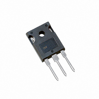
DIODE HEXFRED 1200V 16A TO-247AC
Manufacturer
Vishay
Series
HEXFRED®r
Datasheet
1.HFA16PB120.pdf
(7 pages)
Specifications of HFA16PB120
Voltage - Forward (vf) (max) @ If
3V @ 16A
Voltage - Dc Reverse (vr) (max)
1200V (1.2kV)
Current - Average Rectified (io)
16A
Current - Reverse Leakage @ Vr
20µA @ 1200V
Diode Type
Standard
Speed
Fast Recovery =< 500ns, > 200mA (Io)
Reverse Recovery Time (trr)
135ns
Mounting Type
Through Hole, Radial
Package / Case
TO-247-2 (TO-247AC Modified)
Product
Ultra Fast Recovery Rectifier
Configuration
Single
Reverse Voltage
1200 V
Forward Voltage Drop
3.93 V at 32 A
Recovery Time
135 ns
Forward Continuous Current
16 A
Max Surge Current
190 A
Reverse Current Ir
20 uA
Mounting Style
Through Hole
Maximum Operating Temperature
+ 150 C
Minimum Operating Temperature
- 55 C
Lead Free Status / RoHS Status
Contains lead / RoHS non-compliant
Capacitance @ Vr, F
-
Lead Free Status / RoHS Status
Contains lead / RoHS non-compliant, Lead free / RoHS Compliant
Other names
*HFA16PB120
VS-HFA16PB120
VS-HFA16PB120
VSHFA16PB120
VSHFA16PB120
VS-HFA16PB120
VS-HFA16PB120
VSHFA16PB120
VSHFA16PB120
Available stocks
Company
Part Number
Manufacturer
Quantity
Price
Company:

Part Number:
HFA16PB120
Manufacturer:
IR
Quantity:
10 000
Company:
Part Number:
HFA16PB120PBF
Manufacturer:
MICROCHIP
Quantity:
1 001


Dynamic Recovery Characteristics @ T
HFA16PB120
Thermal - Mechanical Characteristics
Document Number: 93071
Bulletin PD-2.364 rev. A 11/00
Electrical Characteristics @ T
! 0.063 in. from Case (1.6mm) for 10 sec
" Typical Socket Mount
# Mounting Surface, Flat, Smooth and Greased
t
t
t
I
I
Q
Q
di
di
T
R
V
I
C
L
R
R
V
rr
rr1
rr2
RRM1
RRM2
Wt
RM
lead
S
T
rr1
rr2
(rec)M
(rec)M
th
BR
FM
th
th
JC
JA
CS
!
"
#
/dt1
/dt2
Reverse Recovery Time
Peak Recovery Current
Reverse Recovery Charge
Peak Rate of Fall of Recovery Current
During t
See Fig. 5, 10
Cathode Anode Breakdown Voltage
Junction Capacitance
Series Inductance
Max Forward Voltage
Max Reverse Leakage Current
See Fig. 6
See Fig. 7
Parameter
Lead Temperature
Thermal Resistance, Junction to Case
Thermal Resistance, Junction to Ambient
Thermal Resistance, Case to Heat Sink
b
Mounting Torque
Parameter
Weight
Parameter
See Fig. 8
J
= 25°C (unless otherwise specified)
1200
Min Typ Max Units
Min Typ Max Units
J
= 25°C (unless otherwise specified)
0.75
164
260
680 1838
120
375 2000
8.3
5.8
2.5
3.2
2.3
8.0
30
90
76
27
3.93
135
245
675
3.0
2.7
10
15
20
40
Min
6.0
5.0
A/µs
nC
pF
ns
µA
nH
V
V
A
I
T
T
T
T
T
T
T
T
I
I
I
I
V
T
V
Measured lead to lead 5mm from
package body
F
R
F
F
F
J
J
J
J
J
J
J
J
R
J
R
= 1.0A, di
= 125°C
= 125°C
= 125°C
= 125°C
= 25°C
= 25°C
= 25°C
= 25°C
= 16A
= 32A
= 16A, T
= 100µA
= 125°C, V
= V
= 200V
Typ
0.50
0.07
2.0
R
Test Conditions
Rated
Test Conditions
J
f
/dt = 200A/µs, V
= 125°C
R
= 0.8 x V
www.vishay.com
Max
0.83
300
80
12
10
di
f
R
V
/dt = 200A/µs
See Fig. 1
See Fig. 2
See Fig. 3
I
R
Rated
F
= 200V
R
= 16A
= 30V
Units
Kg-cm
lbf•in
K/W
D
(oz)
°C
Rated
g
2
Related parts for HFA16PB120
Image
Part Number
Description
Manufacturer
Datasheet
Request
R

Part Number:
Description:
Ultra High Slew RateOperational Amplifier
Manufacturer:
Intersil Corporation
Part Number:
Description:
Ultra High Slew Rate Operational Amplifier
Manufacturer:
Intersil Corporation
Part Number:
Description:
Ultra High Speed Comparator
Manufacturer:
Intersil Corporation
Part Number:
Description:
Ultra High Speed Comparator
Manufacturer:
Intersil Corporation

Part Number:
Description:
357-036-542-201 CARDEDGE 36POS DL .156 BLK LOPRO
Manufacturer:
Vishay
Datasheet:
Part Number:
Description:
357-036-542-201 CARDEDGE 36POS DL .156 BLK LOPRO
Manufacturer:
Vishay
Datasheet:
Part Number:
Description:
357-036-542-201 CARDEDGE 36POS DL .156 BLK LOPRO
Manufacturer:
Vishay
Datasheet:
Part Number:
Description:
357-036-542-201 CARDEDGE 36POS DL .156 BLK LOPRO
Manufacturer:
Vishay
Datasheet:
Part Number:
Description:
357-036-542-201 CARDEDGE 36POS DL .156 BLK LOPRO
Manufacturer:
Vishay
Datasheet:
Part Number:
Description:
357-036-542-201 CARDEDGE 36POS DL .156 BLK LOPRO
Manufacturer:
Vishay
Datasheet:
Part Number:
Description:
357-036-542-201 CARDEDGE 36POS DL .156 BLK LOPRO
Manufacturer:
Vishay
Datasheet:
Part Number:
Description:
357-036-542-201 CARDEDGE 36POS DL .156 BLK LOPRO
Manufacturer:
Vishay
Datasheet:
Part Number:
Description:
357-036-542-201 CARDEDGE 36POS DL .156 BLK LOPRO
Manufacturer:
Vishay
Datasheet:
Part Number:
Description:
357-036-542-201 CARDEDGE 36POS DL .156 BLK LOPRO
Manufacturer:
Vishay
Datasheet:
Part Number:
Description:
357-036-542-201 CARDEDGE 36POS DL .156 BLK LOPRO
Manufacturer:
Vishay
Datasheet: