D4B-1171N Omron, D4B-1171N Datasheet - Page 14
D4B-1171N
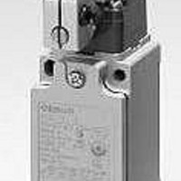
Manufacturer Part Number
D4B-1171N
Description
LSW,PG13.5,SNAP,TOP PLNGR
Manufacturer
Omron
Series
D4B-Nr
Specifications of D4B-1171N
Contact Form
NO / NC
Contact Rating
2 Amps
Actuator
Plunger, Top Roller
Operating Force
18.63 N
Termination Style
Screw
Actuator Style
Top Roller Plunger
Operating Force Max
18.63N
Contact Voltage Ac Max
400V
Contact Voltage Dc Max
250V
Contact Current Ac Max
10A
Contact Current Dc Max
10A
Circuit
DPST (1-NO, 1-NC)
Switch Function
On-Mom, Off-Mom
Contact Rating @ Voltage
10A @ 120VAC
Actuator Type
Roller Plunger
Mounting Type
Chassis Mount
Lead Free Status / RoHS Status
Lead free / RoHS Compliant
Lead Free Status / RoHS Status
Lead free / RoHS Compliant


Precautions
If the D4B-jN is applied to an emergency stop circuit or safety
circuit for prevention of injury, use the D4B-jN model that has an
NC contact equipped with a force-separation mechanism, and
make sure that the D4B-jN operates in the positive mode. In
addition, secure the D4B-jN with screws that are tightened in a
single direction so that the D4B-jN cannot be easily removed.
Then provide a protection cover for the D4B-jN and post a
warning label near the D4B-jN.
In order to protect the D4B-jN from damage due to
short-circuiting, connect a fuse breaking a current 1.5 to 2 times
higher than the rated current in parallel with the D4B-jN.
If an application satisfying EN standards is to employ the D4BL,
apply the 10-A gI or gG fuse approved by IEC269.
Do not apply the D4B-jN to the door without applying a stopper
to the door.
If the D4B-jN is used with the actuator normally pressed, the
D4B-jN may malfunction or may soon have reset failures. Be
sure to check and replace the D4B-jN regularly.
CW, CCW or Two-way Operation
The head of Side Rotary Switches can be converted in seconds to CW, CCW, or two-way operation. The conversion procedure follows.
Head cover (Push and rotate)
Operating position
mark (arrow)
Procedure
1. Remove the head by loosening the four screws that secure it.
2. Turn over the head to set the desired operation (CW, CCW, or both). The desired operation can be
3. Set the CW hole on the head at the operation position mark (arrow) for clockwise operation or set
selected by setting the mode selector knob shown in the figure. This knob is factory set to the
“CW + CCW” (two-way operation) position.
the CCW hole right at the arrow for counterclockwise operation. In either case, be sure to set the
hole position exactly at the arrow point.
15
Tightening Torque
Note: Apply a tightening torque of 0.78 to 0.88 N S m to conduit
Since loose screws may
cause a malfunction,
tighten each screw to the
appropriate torque.
1 Terminal screw (M3.5)
2 Cover-mounting screw
3 Head-mounting screw
4 Switch-mounting screw
5 Connector
6 Cap screw
Type
(see note)
(M5)
(for three-conduit models)
models.
(4)
(3)
(1)
Proper tightening torque
0.59 to 0.78 N S m
1.18 to 1.37 N S m
0.78 to 0.98 N S m
4.90 to 5.88 N S m
1.77 to 2.16 N S m
1.27 to 1.67 N S m
(5)
(2)
D4B-N
Related parts for D4B-1171N
Image
Part Number
Description
Manufacturer
Datasheet
Request
R

Part Number:
Description:
Safety Limit Switch
Manufacturer:
Omron
Datasheet:

Part Number:
Description:
SWITCHES
Manufacturer:
Omron
Datasheet:

Part Number:
Description:
D4B-N BODY ONLY,1NC/1NO,SNAP
Manufacturer:
Omron
Datasheet:
Part Number:
Description:
LIMIT SWITCH
Manufacturer:
Omron
Datasheet:
Part Number:
Description:
LIMIT SWITCH
Manufacturer:
Omron
Datasheet:
Part Number:
Description:
LIMIT SWITCH
Manufacturer:
Omron
Datasheet:
Part Number:
Description:
LIMIT SWITCH
Manufacturer:
Omron
Datasheet:
Part Number:
Description:
LIMIT SWITCH ADJ ROLL LEVER
Manufacturer:
Omron
Datasheet: