HFA15TB60 Vishay, HFA15TB60 Datasheet - Page 2
HFA15TB60
Manufacturer Part Number
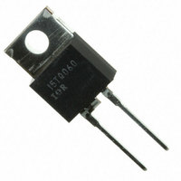
HFA15TB60
Description
DIODE HEXFRED 600V 15A TO-220AC
Manufacturer
Vishay
Series
HEXFRED®r
Datasheet
1.HFA15TB60.pdf
(6 pages)
Specifications of HFA15TB60
Voltage - Forward (vf) (max) @ If
1.7V @ 15A
Voltage - Dc Reverse (vr) (max)
600V
Current - Average Rectified (io)
15A
Current - Reverse Leakage @ Vr
10µA @ 600V
Diode Type
Standard
Speed
Fast Recovery =< 500ns, > 200mA (Io)
Reverse Recovery Time (trr)
60ns
Mounting Type
Through Hole
Package / Case
TO-220-2 Fused Center, TO-220AC
Lead Free Status / RoHS Status
Contains lead / RoHS non-compliant
Capacitance @ Vr, F
-
Other names
*HFA15TB60
VS-HFA15TB60
VS-HFA15TB60
VSHFA15TB60
VSHFA15TB60
VS-HFA15TB60
VS-HFA15TB60
VSHFA15TB60
VSHFA15TB60
Available stocks
Company
Part Number
Manufacturer
Quantity
Price
Company:

Part Number:
HFA15TB60
Manufacturer:
IR
Quantity:
30 500
Company:
Part Number:
HFA15TB60
Manufacturer:
IR
Quantity:
10 000
Company:
Part Number:
HFA15TB60-1
Manufacturer:
IR
Quantity:
10 000
Company:
Part Number:
HFA15TB60PBF
Manufacturer:
IXYS
Quantity:
60 000
Company:
Part Number:
HFA15TB60S
Manufacturer:
IR
Quantity:
10 000


HFA15TB60/HFA15TB60-1
Vishay High Power Products
www.vishay.com
2
ELECTRICAL SPECIFICATIONS (T
PARAMETER
Cathode to anode
breakdown voltage
Maximum forward voltage
Maximum reverse
leakage current
Junction capacitance
Series inductance
DYNAMIC RECOVERY CHARACTERISTICS (T
PARAMETER
Reverse recovery time
See fig. 5
Peak recovery current
See fig. 6
Reverse recovery charge
See fig. 7
Peak rate of fall of recovery
current during t
See fig. 8
THERMAL - MECHANICAL SPECIFICATIONS
PARAMETER
Lead temperature
Thermal resistance,
junction to case
Thermal resistance,
junction to ambient
Thermal resistance,
case to heatsink
Weight
Mounting torque
Marking device
b
dI
dI
SYMBOL
SYMBOL
SYMBOL
(rec)M
(rec)M
I
I
R
R
R
T
RRM1
RRM2
V
V
Q
Q
I
t
t
C
L
thCS
RM
t
lead
thJC
thJA
rr1
rr2
FM
BR
rr
rr1
rr2
S
T
For technical questions, contact: diodes-tech@vishay.com
/dt1
/dt2
I
T
T
T
T
T
T
T
T
0.063" from case (1.6 mm) for 10 s
Typical socket mount
Mounting surface, flat, smooth and gerased
Case style TO-220AC
Case style TO-262
I
I
I
I
V
T
V
Measured lead to lead 5 mm from package body
F
Ultrafast Soft Recovery Diode, 15 A
R
F
F
F
J
J
J
J
J
J
J
J
J
R
R
= 15 A
= 30 A
= 15 A, T
= 1.0 A, dI
= 100 µA
= 25 °C
= 125 °C
= 25 °C
= 125 °C
= 25 °C
= 125 °C
= 25 °C
= 125 °C
= 125 °C, V
J
= V
= 200 V
= 25 °C unless otherwise specified)
R
rated
J
F
TEST CONDITIONS
TEST CONDITIONS
TEST CONDITIONS
= 125 °C
/dt = 200 A/µs, V
R
= 0.8 x V
HEXFRED
J
= 25 °C unless otherwise specified)
R
I
dI
V
F
rated
R
F
= 15 A
/dt = 200 A/µs
= 200 V
R
= 30 V
®
See fig. 1
See fig. 2
See fig. 3
MIN.
MIN.
MIN.
(5.0)
600
6.0
-
-
-
-
-
-
-
-
-
-
-
-
-
-
-
-
-
-
-
-
-
-
TYP.
TYP.
TYP.
0.07
241
188
160
400
4.0
6.5
0.5
2.0
HFA15TB60-1
1.3
1.5
1.2
1.0
8.0
19
42
74
84
25
HFA15TB60
-
-
-
-
-
Document Number: 93063
MAX.
MAX.
MAX.
1000
Revision: 30-Jul-08
(10)
120
180
600
300
1.7
2.0
1.6
6.0
1.7
10
50
60
10
80
12
-
-
-
-
-
-
-
-
kgf · cm
(lbf · in)
UNITS
UNITS
UNITS
A/µs
K/W
oz.
µA
pF
nH
nC
ns
°C
V
A
g
Related parts for HFA15TB60
Image
Part Number
Description
Manufacturer
Datasheet
Request
R

Part Number:
Description:
357-036-542-201 CARDEDGE 36POS DL .156 BLK LOPRO
Manufacturer:
Vishay
Datasheet:
Part Number:
Description:
357-036-542-201 CARDEDGE 36POS DL .156 BLK LOPRO
Manufacturer:
Vishay
Datasheet:
Part Number:
Description:
357-036-542-201 CARDEDGE 36POS DL .156 BLK LOPRO
Manufacturer:
Vishay
Datasheet:
Part Number:
Description:
357-036-542-201 CARDEDGE 36POS DL .156 BLK LOPRO
Manufacturer:
Vishay
Datasheet:
Part Number:
Description:
357-036-542-201 CARDEDGE 36POS DL .156 BLK LOPRO
Manufacturer:
Vishay
Datasheet:
Part Number:
Description:
357-036-542-201 CARDEDGE 36POS DL .156 BLK LOPRO
Manufacturer:
Vishay
Datasheet:
Part Number:
Description:
357-036-542-201 CARDEDGE 36POS DL .156 BLK LOPRO
Manufacturer:
Vishay
Datasheet:
Part Number:
Description:
357-036-542-201 CARDEDGE 36POS DL .156 BLK LOPRO
Manufacturer:
Vishay
Datasheet:
Part Number:
Description:
357-036-542-201 CARDEDGE 36POS DL .156 BLK LOPRO
Manufacturer:
Vishay
Datasheet:
Part Number:
Description:
357-036-542-201 CARDEDGE 36POS DL .156 BLK LOPRO
Manufacturer:
Vishay
Datasheet:
Part Number:
Description:
357-036-542-201 CARDEDGE 36POS DL .156 BLK LOPRO
Manufacturer:
Vishay
Datasheet:
Part Number:
Description:
357-036-542-201 CARDEDGE 36POS DL .156 BLK LOPRO
Manufacturer:
Vishay
Datasheet:
Part Number:
Description:
357-036-542-201 CARDEDGE 36POS DL .156 BLK LOPRO
Manufacturer:
Vishay
Datasheet:
Part Number:
Description:
357-036-542-201 CARDEDGE 36POS DL .156 BLK LOPRO
Manufacturer:
Vishay
Datasheet:
Part Number:
Description:
357-036-542-201 CARDEDGE 36POS DL .156 BLK LOPRO
Manufacturer:
Vishay
Datasheet: