10ETF04 Vishay, 10ETF04 Datasheet - Page 3
10ETF04
Manufacturer Part Number
10ETF04
Description
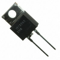
DIODE FAST REC 400V 10A TO-220AC
Manufacturer
Vishay
Datasheet
1.10ETF02.pdf
(8 pages)
Specifications of 10ETF04
Diode Type
Standard
Voltage - Forward (vf) (max) @ If
1.2V @ 10A
Voltage - Dc Reverse (vr) (max)
400V
Current - Average Rectified (io)
10A
Current - Reverse Leakage @ Vr
100µA @ 400V
Speed
Fast Recovery =< 500ns, > 200mA (Io)
Reverse Recovery Time (trr)
145ns
Mounting Type
Through Hole
Package / Case
TO-220-2 Fused Center, TO-220AC
Repetitive Reverse Voltage Vrrm Max
400V
Forward Current If(av)
10A
Forward Voltage Vf Max
1.2V
Reverse Recovery Time Trr Max
145ns
Forward Surge Current Ifsm Max
150A
Product
Fast Recovery Rectifier
Configuration
Single
Reverse Voltage
400 V
Forward Voltage Drop
1.2 V
Recovery Time
145 ns
Forward Continuous Current
10 A
Max Surge Current
150 A
Reverse Current Ir
100 uA
Mounting Style
Through Hole
Maximum Operating Temperature
+ 150 C
Minimum Operating Temperature
- 40 C
Lead Free Status / RoHS Status
Contains lead / RoHS non-compliant
Capacitance @ Vr, F
-
Lead Free Status / Rohs Status
No RoHS Version Available
Other names
*10ETF04
Available stocks
Company
Part Number
Manufacturer
Quantity
Price
Company:

Part Number:
10ETF04
Manufacturer:
IR
Quantity:
18 500
Company:
Part Number:
10ETF04FP
Manufacturer:
IR
Quantity:
13 400
Company:
Part Number:
10ETF04S
Manufacturer:
IR
Quantity:
12 500
Company:
Part Number:
10ETF04SPBF
Manufacturer:
VISHAY
Quantity:
12 000
Company:
Part Number:
10ETF04STRFPBF
Manufacturer:
IR
Quantity:
13 400


Document Number: 93132
Thermal-Mechanical Specifications
T
T
R
R
R
wt
T
J
stg
thJC
thJA
thCS
1 5 0
1 4 5
1 4 0
1 3 5
1 3 0
1 2 5
1 2 0
1 6
1 4
1 2
1 0
8
6
4
2
0
Parameters
Max. Junction Temperature Range
Max. Storage Temperature Range
Max. Thermal Resistance Junction
to Case
Max. Thermal Resistance Junction
to Ambient
Typical Thermal Resistance, Case to
Heatsink
Approximate Weight
Mounting Torque
Case Style
Fig. 3 - Forward Power Loss Characteristics
0
0
Fig. 1 - Current Rating Characteristics
A vera g e Forw a rd C urren t (A )
A verag e Forw a rd C urrent (A)
2
2
RM S Lim it
18 0
12 0
9 0
6 0
3 0
4
3 0
4
10ETF.. Series
R
thJ C
6
6 0
C o nd uction A ng le
C o nd uc tio n A ngle
(D C ) = 1.5 C /W
10E TF.. Series
T = 150 C
6
90
J
8
Min.
Max.
1 2 0
8
1 80
10
- 40 to 150
- 40 to 150
10ETF..
2 (0.07)
12 (10)
12
1 0
6 (5)
1.5
TO-220AC
0.5
62
Units
Kg-cm
(Ibf-in)
g (oz.)
°C/W
°C/W
°C/W
°C
°C
DC operation
Mounting surface , smooth and greased
JEDEC
Conditions
15 0
14 5
14 0
13 5
13 0
12 5
12 0
2 0
1 6
1 2
8
4
0
10ETF.. QUIET
Fig. 4 - Forward Power Loss Characteristics
0
0
RM S Lim it
Fig. 2 - Current Rating Characteristics
180
120
2
D C
90
60
30
A verag e Forw ard C urren t (A)
A vera g e Forw a rd C urren t (A)
Bulletin I2137 rev. B 10/00
3 0
4
4
6 0
6
10ETF.. Series
R
thJ C
9 0
8
8
12 0
(D C ) = 1.5 C /W
C o nd u ction P e rio d
www.vishay.com
C o nd u ctio n P e rio d
1 0
IR
10ETF .. Series
T = 150 C
J
1 8 0
1 2
1 2
Series
D C
1 4
3
16
1 6
Related parts for 10ETF04
Image
Part Number
Description
Manufacturer
Datasheet
Request
R


Part Number:
Description:
10 A, 40V Schottky Rectifier
Manufacturer:
MULTICOMP
Datasheet:

Part Number:
Description:
357-036-542-201 CARDEDGE 36POS DL .156 BLK LOPRO
Manufacturer:
Vishay
Datasheet:
Part Number:
Description:
357-036-542-201 CARDEDGE 36POS DL .156 BLK LOPRO
Manufacturer:
Vishay
Datasheet:
Part Number:
Description:
357-036-542-201 CARDEDGE 36POS DL .156 BLK LOPRO
Manufacturer:
Vishay
Datasheet:
Part Number:
Description:
357-036-542-201 CARDEDGE 36POS DL .156 BLK LOPRO
Manufacturer:
Vishay
Datasheet:
Part Number:
Description:
357-036-542-201 CARDEDGE 36POS DL .156 BLK LOPRO
Manufacturer:
Vishay
Datasheet:
Part Number:
Description:
357-036-542-201 CARDEDGE 36POS DL .156 BLK LOPRO
Manufacturer:
Vishay
Datasheet:
Part Number:
Description:
357-036-542-201 CARDEDGE 36POS DL .156 BLK LOPRO
Manufacturer:
Vishay
Datasheet:
Part Number:
Description:
357-036-542-201 CARDEDGE 36POS DL .156 BLK LOPRO
Manufacturer:
Vishay
Datasheet:
Part Number:
Description:
357-036-542-201 CARDEDGE 36POS DL .156 BLK LOPRO
Manufacturer:
Vishay
Datasheet:
Part Number:
Description:
357-036-542-201 CARDEDGE 36POS DL .156 BLK LOPRO
Manufacturer:
Vishay
Datasheet:
Part Number:
Description:
357-036-542-201 CARDEDGE 36POS DL .156 BLK LOPRO
Manufacturer:
Vishay
Datasheet:
Part Number:
Description:
357-036-542-201 CARDEDGE 36POS DL .156 BLK LOPRO
Manufacturer:
Vishay
Datasheet: