A22Z-3466-1 Omron, A22Z-3466-1 Datasheet - Page 16
A22Z-3466-1
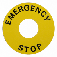
Manufacturer Part Number
A22Z-3466-1
Description
LEGEND PLATE
Manufacturer
Omron
Type
Round Plate for Emergency Stop Switchr
Series
A22Er
Specifications of A22Z-3466-1
Accessory Type
Emergency Stop Plate
Illumination
Not Illuminated
Features
"Emergency Stop" Plate
Lead Free Status / RoHS Status
Lead free / RoHS Compliant
For Use With
Z1501 - SWITCH PB RND MOM SPST-NO ILLZ1496 - SWITCH PB RND MOM SPST-NO ILLZ1500 - SWITCH PB RND MOM SPST-NO ILLZ1495 - SWITCH PB ILL RND MOM SPST-NOZ1497 - SWITCH PB RND MOM SPST-NC ILLZ1492 - SWITCH PB RND MOM SPST-NC ILLZ1499 - SWITCH PB RND MOM SPST-NO ILLZ1494 - SWITCH PB ILL RND MOM SPST-NOZ1498 - SWITCH PB RND MOM SPST-NO ILLZ1493 - SWITCH PB RND MOM SPST-NO ILLZ1491 - SWITCH PB RND MOM SPST-NO ILLZ1486 - SWITCH PB ILL RND MOM SPST-NOZ1490 - SWITCH PB RND MOM SPST-NO ILLZ1485 - SWITCH PB ILL RND MOM SPST-NOZ1487 - SWITCH PB RND MOM SPST-NC ILLZ1482 - SWITCH PB RND MOM SPST-NC ILLZ1489 - SWITCH PB RND MOM SPST-NO ILLZ1484 - SWITCH PB ILL RND MOM SPST-NOZ1488 - SWITCH PB RND MOM SPST-NO ILLZ1483 - SWITCH PB RND MOM SPST-NO ILLZ1481 - SWITCH PB SQ MOM SPST-NO ILL-YLWZ1477 - SWITCH PB SQ MOM SPST-NO ILL-YLWZ1480 - SWITCH PB SQ MOM SPST-NO ILL-WHTZ1476 - SWITCH PB SQ MOM SPST-NO ILL-WHTZ1479 - SWITCH PB SQ MOM SPST-NO ILL-GRNZ1475 - SWITCH PB SQ MOM SPST-NO ILL-GRNZ1478 - SWITCH PB SQ MOM SPST-NO ILL-BLUZ1474 - SWITCH PB SQ MOM SPST-NO ILL-BLUZ1473 - SWITCH PB SQ MOM SPST-NC ILL-REDZ1472 - SWITCH PB SQ MOM SPST-NC ILL-REDZ1453 - SWTCH PB RND MOM SPST-NO/NC REDZ1452 - SWITCH PB RND MOM SPST-NC REDZ1471 - SWITCH PB MUSH MOM SPST-NO YELLWZ1470 - SWITCH PB MUSH MOM SPST-NO WHITEZ1466 - SWITCH PB MUSH MOM SPST-NC REDZ1469 - SWITCH PB MUSH MOM SPST-NO GREENZ1468 - SWITCH PB MUSH MOM SPST-NO BLACKZ1467 - SWITCH PB MUSH MOM SPST-NO BLUEZ1465 - SWITCH PB MUSH MOM SPST-NO YELLWZ1464 - SWITCH PB MUSH MOM SPST-NO WHITEZ1460 - SWITCH PB MUSH MOM SPST-NC REDZ1463 - SWITCH PB MUSH MOM SPST-NO GREENZ1462 - SWITCH PB MUSH MOM SPST-NO BLACKZ1461 - SWITCH PB MUSH MOM SPST-NO BLUEZ1459 - SWITCH PB RND MOM SPST-NO YELLOWZ1458 - SWITCH PB RND MOM SPST-NO WHITEZ1457 - SWITCH PB RND MOM SPST-NO REDZ1456 - SWITCH PB RND MOM SPST-NO GREENZ1455 - SWITCH PB RND MOM SPST-NO BLACKZ1454 - SWITCH PB RND MOM SPST-NO BLUEZ1451 - SWITCH PB RND MOM SPST-NO YELLOWZ1450 - SWITCH PB RND MOM SPST-NO WHITEZ1449 - SWITCH PB RND MOM SPST-NO REDZ1448 - SWITCH PB RND MOM SPST-NO GREENZ1447 - SWITCH PB RND MOM SPST-NO BLACKZ1446 - SWITCH PB RND MOM SPST-NO BLUEZ1444 - SWITCH PB SQ MOM SPST-NO YELLOWZ1443 - SWITCH PB SQ MOM SPST-NO WHITEZ1445 - SWITCH PB SQ MOM SPST-NO/NC REDZ1442 - SWITCH PB SQ MOM SPST-NO GREENZ1441 - SWITCH PB SQ MOM SPST-NO BLACKZ1440 - SWITCH PB SQ MOM SPST-NO BLUEZ1571 - SWITCH PB SQ MOM SPST-NO/NC YLWZ1565 - SWITCH PB SQ MOM SPST-NO YELLOWZ1570 - SWITCH PB SQ MOM SPST-NO/NC WHTZ1564 - SWITCH PB SQ MOM SPST-NO WHITEZ1569 - SWITCH PB SQ MOM SPST-NO/NC REDZ1438 - SWITCH PB SQ MOM SPST-NC REDZ1572 - SWITCH PB SQ LTCH SPST-NC REDZ1568 - SWITCH PB SQ MOM SPST-NO/NC GRNZ1563 - SWITCH PB SQ MOM SPST-NO GREENZ1567 - SWITCH PB SQ MOM SPST-NO/NC BLKZ1573 - SWITCH PB SQ LTCH SPST-NO/NC BLKZ1562 - SWITCH PB SQ MOM SPST-NO BLACKZ1566 - SWITCH PB SQ MOM SPST-NO/NC BLUEZ1561 - SWITCH PB SQ MOM SPST-NO BLUE
For Use With/related Products
A22 Series
Lead Free Status / Rohs Status
Lead free / RoHS Compliant
Other names
A22Z34661
Z1555
Z1555


Installation
Mounting to the Panel
• The panel dimensions are shown below.
• The panel thickness must be 1 to 5 mm.
• Always use a 25-mm-dia. Lock Ring for a 25-mm-dia. hole.
• When painting or coating the panel, make sure that the specified panel
• Insert the Operation Unit from the front surface of the panel, insert the Lock
• When using a Legend Plate Frame, put one rubber washer each between
• Align the Lock Ring with the groove in the casing, then insert the Lock Ring
• Tighten the mounting nut at a torque of 0.98 to 1.96 N·m.
• When using a Lock Ring, replace with the supplied Lock Ring, insert the
1. When the panel cutout dimension
IP65 degree of protection will be lost if the 25-mm-dia. Lock Ring is not
used because of the larger size of a 25-mm-dia. hole.
dimensions apply to the panel after painting or coating.
Ring and the mounting nut from the terminal side, then tighten the nut.
Before tightening, check that the rubber washer is present between the
Operation Unit and the panel.
the Legend Plate Frame and the panel and between the Operation Unit and
the Legend Plate Frame. (One rubber washer will be provided when one
Legend Plate Frame is ordered.)
so that its edge is located on the panel side.
projecting part into the lock slot, and then tighten the mounting nut.
is 25 dia., remove the supplied
rubber washer and mount the 25-
dia. Ring as shown below. (Since
the A22Z-R25 is not attached to
the main body, order separately.)
3.2
+0.2
0
With Lock Ring
Hold here
(3) Mounting the Operation Unit on the Panel
22.3 dia.
22.3 dia.
25 dia.
25 dia.
22 dia.
22.3
+0.4
0
R0.8 max.
dia.
Operation Unit
25-dia. Ring
(A22Z-R25)
(1) Preparing the Panel
24.1
Mounting nut
0.5
http://www.ia.omron.com/
Rubber washer
Lock Ring
Panel
Panel
+0.4
1.3
0
Lock Ring
Mounting nut
2. When the panel cutout
22.3
dimension is 25 dia., remove the
supplied rubber washer and
mount the 25-dia. Ring as shown
below. (Since the A22Z-R25 is
not attached to the main body,
order separately.)
+0.4
Without Lock Ring
0
dia.
Pro-
jecting
part
25
Panel
Rubber washer
(mounted to
Operation Unit)
30-dia.
Resin Attachment
(A22Z-A30)
Operation Unit
Rubber washer
(included)
Mounting
Ring
+0.5
Lock Ring
0
Lock Ring
dia.
Mounting
panel
• Insert the Operation Unit into the Switch Unit, aligning the arrow mark inscribed on
• Move the lever in the direction indicated by the arrow in the following figure, then pull
1. The following diagram provides
Dimensions A and B between mounting hole centers are given in the following tables.
For 1., Above
For 2., Above
Note: 1. The above dimensions are the minimum dimensions when using the
A22-10, A22-10S, A22-01, A22-01S
A22-20, A22-20S, A-22-02, A22-02S, A22-11, A22-11S
Naked crimp terminals
Crimp terminals with
insulating sheaths
the Case with the lever on the Switch Blocks, then move the lever in the direction
indicated by the arrow in the following figure.
the Operation Unit or the Switch Blocks.
Since the lever has a hole with an inside diameter of 6.5 mm, the lever can be moved
in the specified direction by inserting a screwdriver into the hole and then moving the
screwdriver.
Type of crimp terminal
the dimensions for mounting
individual Switches, Legend
Plates, and Lock Rings with leads
connected directly to Switch
terminals.
2. When using pushbuttons exceeding 30 mm, adjust dimension A or B
applicable wiring materials listed on page 19. If any other materials are used,
check the suitability of dimensions in advance.
accordingly. (When mounting the A22-M@ in a matrix, “30 mm” would have
to be increased to 40 mm.
(4) Mounting the Switch on the Operation Unit
30
(c)Copyright OMRON Corporation 2007 All Rights Reserved.
Switch model
(5) Removing the Switch
A22-10, A22-10S, A22-01, A22-01S
A22-20, A22-20S, A22-02, A22-02S,
A22-11, A22-11S
A22-10, A22-10S, A22-01, A22-01S
A22-20, A22-20S, A22-02, A22-02S,
A22-11, A22-11S
(2) Matrix Mounting
A
Switch model
2. The following diagram provides the
dimensions for mounting Large Legend
Plates with crimp terminals connected
to Switch terminals.
Operation Unit
Arrow mark
Screwdriver
30
Lever
Dimension B
51 mm min.
61 mm min.
60 mm min.
70 mm min.
Dimension A
45 mm min.
55 mm min.
A22E
B
16
Related parts for A22Z-3466-1
Image
Part Number
Description
Manufacturer
Datasheet
Request
R

Part Number:
Description:
CONTROL BOX 3 HOLES A22 SERIES
Manufacturer:
Omron
Datasheet:

Part Number:
Description:
CHARACTER FILM ROUND "START" A22
Manufacturer:
Omron
Datasheet:
Part Number:
Description:
LEGEND PLATE STD "START" A22 SER
Manufacturer:
Omron
Datasheet:

Part Number:
Description:
CONTROL BOX 1 HOLE A22 SERIES
Manufacturer:
Omron
Datasheet:

Part Number:
Description:
CONTROL BOX 2 HOLES A22 SERIES
Manufacturer:
Omron
Datasheet:

Part Number:
Description:
PB ENCL. 1 HOLE YELLOW
Manufacturer:
Omron
Datasheet:

Part Number:
Description:
RING FOR 25MM A22 SERIES PANEL
Manufacturer:
Omron
Datasheet:
Part Number:
Description:
CHARACTER FILM SQUARE A22 SERIES
Manufacturer:
Omron
Datasheet:
Part Number:
Description:
COLOR LENS FOR PB SWITCH BLUE
Manufacturer:
Omron
Datasheet:
Part Number:
Description:
COLOR LENS FOR PB SWITCH GREEN
Manufacturer:
Omron
Datasheet:
Part Number:
Description:
SWITCH PB RND MOM SPST-NO/NC RED
Manufacturer:
Omron
Datasheet:

Part Number:
Description:
SWITCH PB ROUND ALT SPST-NO BLUE
Manufacturer:
Omron
Datasheet:

Part Number:
Description:
SWITCH PB ROUND ALT SPST-NO BLK
Manufacturer:
Omron
Datasheet:

Part Number:
Description:
SWITCH PB ROUND ALT SPST-NO GRN
Manufacturer:
Omron
Datasheet:

Part Number:
Description:
SWITCH PB ROUND ALT SPST-NO RED
Manufacturer:
Omron
Datasheet: